Developer container, developing apparatus, process cartridge, apparatus main body, and image forming apparatus

a technology for developing apparatuses and containerized containers, which is applied in the direction of electrographic process apparatuses, instruments, optics, etc., can solve the problems of unstable state of developer and difficulty in detecting developer amounts with accuracy, and achieve the effect of improving accuracy of developer amount detection using stirring members and electrodes provided in the developer housing chamber

Active Publication Date: 2016-08-04
CANON KK
View PDF5 Cites 11 Cited by
  • Summary
  • Abstract
  • Description
  • Claims
  • Application Information

AI Technical Summary

Benefits of technology

[0008]An object of the present invention is to provide a technique capable of improving accuracy of developer amount detection using a stirring member and electrodes provided in a developer housing chamber.
[0025]According to the present invention, accuracy of developer amount detection using a stirring member and electrodes provided in a developer housing chamber can be improved.

Problems solved by technology

However, when a detecting portion is provided in a container in which developer is stirred by a stirring member, in particular, a state of the developer does not stabilize because the developer is being stirred.
Therefore, it is difficult to detect a developer amount with accuracy.

Method used


Image

  • Developer container, developing apparatus, process cartridge, apparatus main body, and image forming apparatus
  • Developer container, developing apparatus, process cartridge, apparatus main body, and image forming apparatus
  • Developer container, developing apparatus, process cartridge, apparatus main body, and image forming apparatus

Examples


first embodiment

Outline of Configurations and Operations of Image Forming Apparatus and Process Cartridge

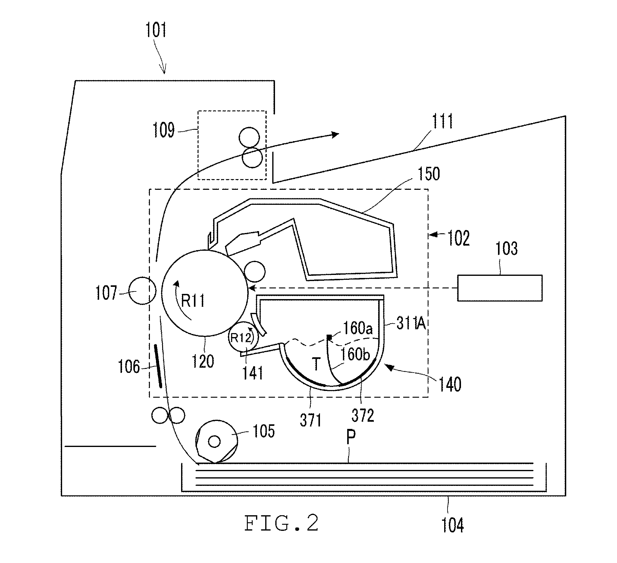
[0056]FIG. 2 is a schematic sectional view showing a schematic configuration of an image forming apparatus according to an embodiment of the present invention. The image forming apparatus is a laser beam printer adopting an electrophotographic system and an attachable / detachable process cartridge system. A printer receives and prints image information by being connected to an external host apparatus such as a personal computer or an image reading apparatus. Reference numeral 101 denotes a printer main body (an image forming apparatus main body) and 102 denotes a process cartridge attachable / detachable to / from the printer main body 101.

[0057]FIG. 3 is a schematic sectional view of a process cartridge according to the first embodiment which will be used to describe the process cartridge 102. Reference numeral 120 denotes a drum-type electrophotographic photosensitive body (hereinafter, referred to...

second embodiment

[0095]A second embodiment of the present invention differs from the first embodiment in a configuration of a developer container. Hereinafter, differences from the first embodiment will be described and matters that are similar to those of the first embodiment will not be described. It is to be understood that matters not described here are similar to those described in the first embodiment.

[0096]FIG. 8 is a schematic sectional view of a developing apparatus 180 according to the second embodiment. The second embodiment differs from the first embodiment in that the developer container has a different toner capacity and, accordingly, a stirring member and an electrode have been added. Specifically, in the developing apparatus 180 according to the present embodiment, two stirring members 181 and 185 are respectively rotatably provided in a toner supply chamber 187 and, at the same time, three antenna members 182 to 184 are installed on a bottom surface of the toner supply chamber 187.

[...

third embodiment

Configuration of Image Forming Apparatus and Image Forming Process

[0111]FIG. 11 is a schematic sectional view showing a schematic configuration of an image forming apparatus according to an embodiment of the present invention. The image forming apparatus is a laser beam printer adopting an electrophotographic system. The image forming apparatus is capable of outputting an image based on image information sent from a connected external host apparatus such as a personal computer or an image reading apparatus.

[0112]The image forming apparatus according to the present embodiment can be used by selectively mounting a cartridge A2 (FIG. 12) and a cartridge B2 (FIG. 13) on an image forming apparatus main body (hereinafter, referred to as an apparatus main body) 2100. In this case, the cartridge A2 is a process cartridge with a small developer housing amount and the cartridge B2 is a process cartridge with a large developer housing amount. In addition, the cartridges A2 and B2 are respectiv...


PUM


Abstract

A developer container includes: a housing chamber 147 which includes an opening 145 and which houses developer; a stirring member 160 which includes a sheet-like stirring portion 160b and a rotary shaft 160a to which the stirring portion 160b is attached; and a first electrode 143 and a second electrode 144 which are used to detect an amount of the developer and which are arranged with an interval therebetween, where in an area X1 between the first electrode 143 and the second electrode 144 in the housing chamber 147 is positioned below the rotary shaft 160a of the stirring member 160, and the sheet-like stirring portion 160b comes into contact with the area X1 due to rotation of the stirring member 160.

Description

BACKGROUND OF THE INVENTION[0001]1. Field of the Invention[0002]The present invention relates to a developer container, a developing apparatus, a process cartridge, an apparatus main body, and an image forming apparatus. Here, a developing apparatus at least includes a developer bearing member that bears developer. Alternatively, a developing apparatus may also include a frame body for housing developer (developer container), a conveying member for conveying the developer, and the like. A cartridge is a piece of equipment which integrates a plurality of components in an image forming apparatus and which is attachable / detachable to / from a main body of the image forming apparatus. A process cartridge at least includes an image bearing member that bears a developer image. In particular, a cartridge which is obtained by integrating an image bearing member and processing means that acts on the image bearing member is referred to as a process cartridge. An image forming apparatus is an ap...

Claims


Application Information

Patent Timeline
Patent Type & Authority Applications(United States)
IPC IPC(8): G03G15/08
CPCG03G15/086G03G2215/085G03G15/0889G03G15/556G03G15/0856G03G2215/0888
Inventor KATO, MASAHITOSHIBUKAWA, KENTAYAMAUCHI, KAZUMIABE, KATSUICHIASANUMA, NAOYATODA, ATSUSHIKISHI, YOSUKEFUKUSHIMA, NAOKI
Owner CANON KK
Why Eureka
Try Eureka