
Force feedback system including multi-tasking graphical host environment

a feedback system and host environment technology, applied in the field of interface devices, can solve problems such as the distortion of force from such a change in aspect ratio, and achieve the effect of maximum compatibility and great flexibility

Inactive Publication Date: 2016-08-04
IMMERSION CORPORATION
View PDF0 Cites 10 Cited by
  • Summary
  • Abstract
  • Description
  • Claims
  • Application Information

AI Technical Summary

Benefits of technology

The patent describes a force feedback system that allows a host computer to interface with a force feedback device without conflicts. The force feedback device offers both relative and absolute position reporting, providing flexibility for different applications. It also includes information about ballistic parameters and screen size to accurately determine mouse and graphical object positions in the force feedback environment. The patent further describes force feedback effects and structures such as events and enclosures. The technical effects of this system include improved control and precision in user interactions through force feedback.

Problems solved by technology

A different problem occurs when using a force feedback device with a GUI.
Another problem occurs when force feedback is implemented with a GUI or other graphical environment and the graphical environment changes resolution or aspect ratio.
Using prior art force feedback devices, forces can become distorted from such an aspect ratio change.

Method used


Image

  • Force feedback system including multi-tasking graphical host environment
  • Force feedback system including multi-tasking graphical host environment
  • Force feedback system including multi-tasking graphical host environment

Examples


embodiment 290

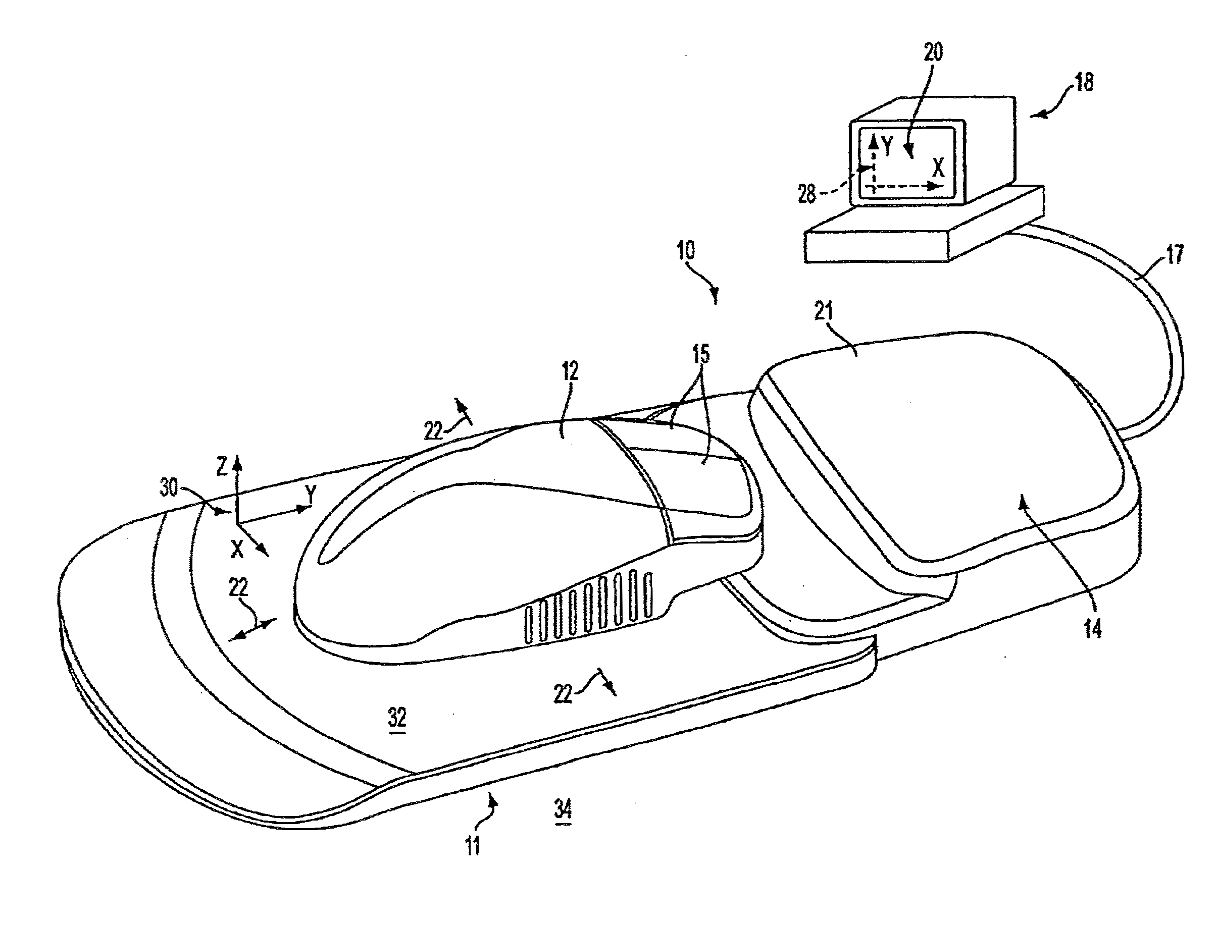
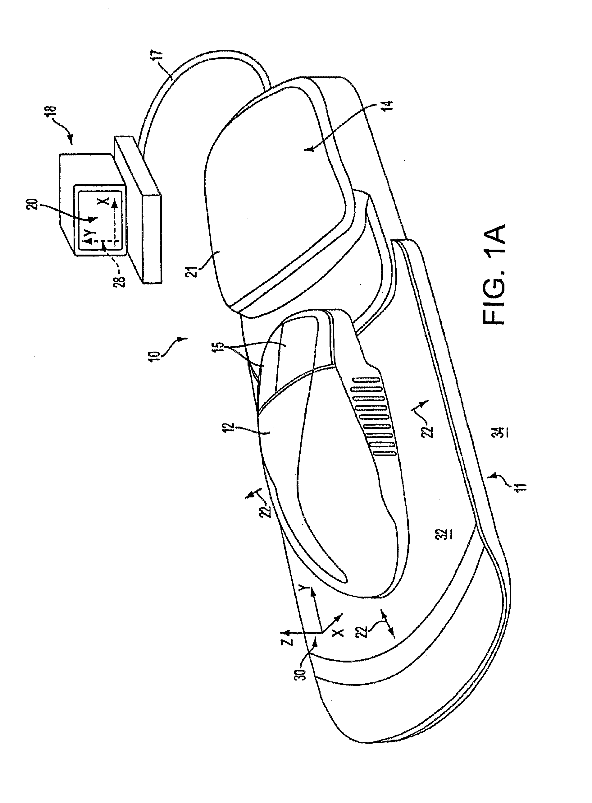
[0189]FIG. 9 is a block diagram illustrating an embodiment 290. In this embodiment, both relative and absolute position reporting modes are used. As referred to herein, relative position reporting means that the force feedback device reports only changes in position of the user object 12 to the host computer, i.e., a difference between a new position and the last reported position, while absolute position reporting means that absolute coordinates are reported to the host from which the host can directly display the graphical object. Most force feedback controllers use absolute position reporting since the position of the graphical object on the screen must be known to implement forces.

[0190]With absolute position reporting, the host computer cannot detect the force feedback device as a standard input controller, such as a mouse, touch screen, or other user device. If relative position reporting were provided, the host computer can detect the force feedback user device as a tradition...

embodiment 400

[0219]FIG. 12 is a block diagram of a method for reporting positions to a host computer from a force feedback device in accordance with an embodiment. Embodiment 400 provides relative position reporting from the force feedback device 11 to the host computer 18. This is advantageous in that the force feedback device is detected by the host as a standard non-force-feedback, where the host computer can use standard drivers and other software. This allows the user to control GUI functions even when force feedback is not currently active, such as during startup of the device or during failures of the force feedback functionality. In addition, a relative position reporting process is more appropriate than an absolute position reporting process for such interface devices as trackballs, in which an unrestricted workspace and range of motion is provided for the user object 12. For example, the spherical ball in a trackball controller, dexterous glove, or wireless game controller can be moved...


PUM


Abstract

A force feedback system provides components for use in a force feedback system including a host computer and a force feedback interface device. An architecture for a host computer allows multi-tasking application programs to interface with the force feedback device without conflicts. One embodiment of a force feedback device provides both relative position reporting and absolute position reporting to allow great flexibility. A different device embodiment provides relative position reporting device allowing maximum compatibility with existing software. Information such as ballistic parameters and screen size sent from the host to the force feedback device allow accurate mouse positions and graphical object positions to be determined in the force feedback environment. Force feedback effects and structures are further described, such as events and enclosures.

Description

CROSS-REFERENCES TO RELATED APPLICATIONS[0001]This application is a continuation of U.S. patent application Ser. No. 14 / 589,355, filed Jan. 5, 2015 and entitled “Force Feedback System including Multi-Tasking Graphical Host Environment,” which is a continuation of U.S. patent application Ser. No. 13 / 225,899, filed Sep. 6, 2011 and entitled “Force Feedback System Including Multi-Tasking Graphical Host Environment,” which is a continuation of U.S. patent application Ser. No. 11 / 824,593, filed Jun. 28, 2007, now U.S. Pat. No. 8,020,095, issued Sep. 13, 2011, and entitled “Force Feedback System including Multi-Tasking Graphical Host Environment,” which is a continuation-in-part of U.S. patent application Ser. No. 11 / 504,131, filed Aug. 14, 2006, now U.S. Pat. No. 8,527,873, issued Sep. 3, 2013, and entitled “Force Feedback System Including Multi-Tasking Graphical Host Environment and Interface Device,” which is a continuation of U.S. application Ser. No. 09 / 974,197, filed Oct. 9, 2001, n...

Claims


Application Information

Patent Timeline
Patent Type & Authority Applications(United States)
IPC IPC(8): G06F3/01G06F3/0481G06F3/0354
CPCG06F3/016G06F2203/014G06F3/0481G06F3/03543G06F3/04812
Inventor BRAUN, ADAM C.BEAMER, JONATHAN L.CHANG, DEAN C.
Owner IMMERSION CORPORATION
Learn More