

Mold in place system and method of making confectionery products
- Summary
- Abstract
- Description
- Claims
- Application Information
AI Technical Summary
Benefits of technology
Problems solved by technology
Method used
Image

Examples
first embodiment
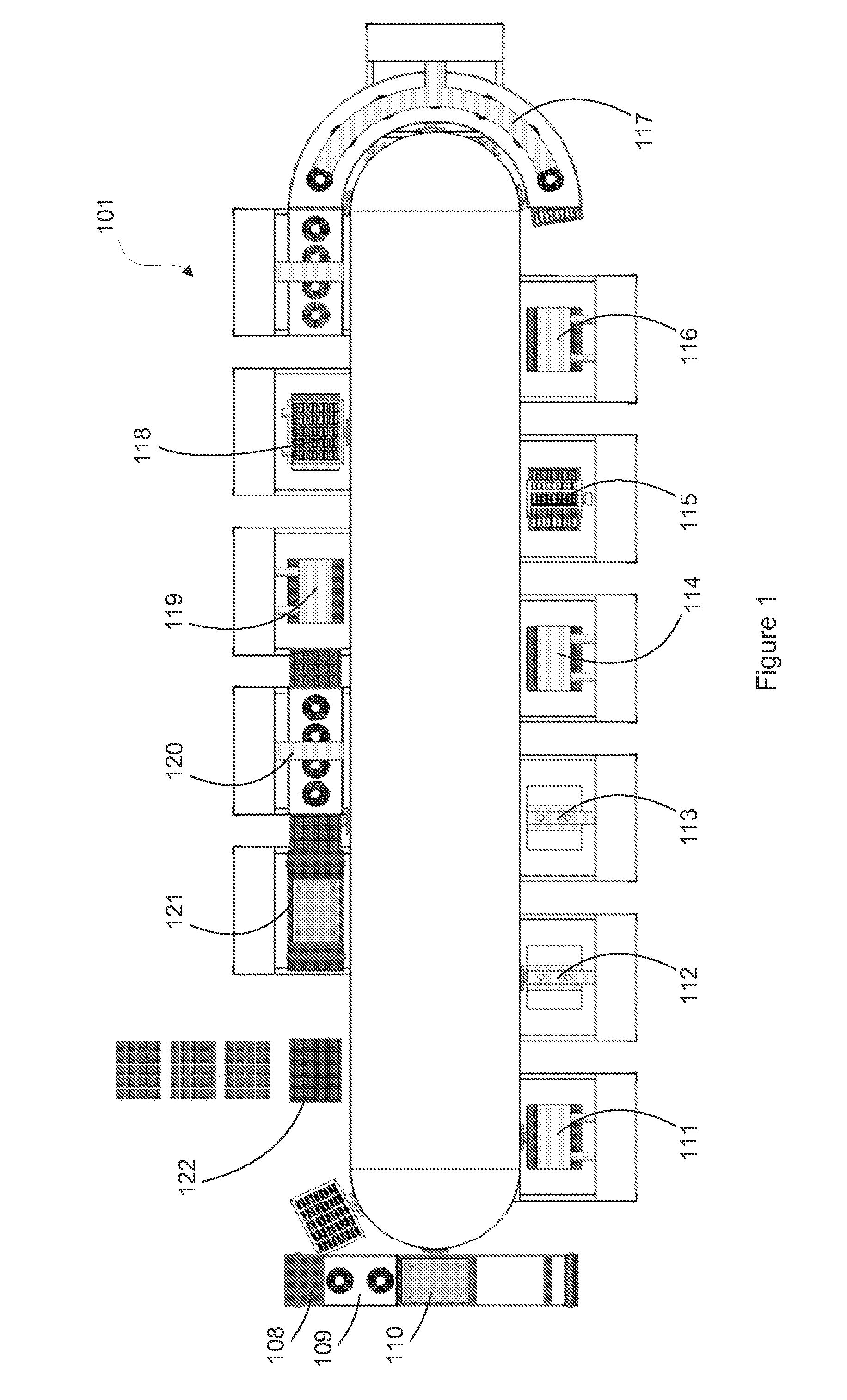
[0077]Referring to FIG. 1, a production line 101 for forming confectionery products, comprising a plurality of stations, will be described in detail. In this embodiment, the line 101 comprises—in sequential order—a film and frame loading station 108, a thermoforming station 110, a depositor station 111, cold stamping stations 112,113, a filling A station 114, a wafer / biscuit station 115, a filling B station 116, a cooling station 117, an inserter station 118, a deposit station 119, a cooling station 120, a sealing station 121, and a cut station 122. Packing of the product and additional cooling steps (not shown) will often be performed after the product has been cut at the cut station 122.
[0078]The arrangement of stations between the thermoforming station 110 and the sealing station 121 will depend upon the product being made. For example, a filled chocolate product may require the depositor station 111 (to deposit chocolate), cold stamping station 112 (to form the deposited chocola...
second embodiment
[0095]Referring now to FIGS. 8-10, a line 201 for forming confectionery products in place, comprising a plurality of stations, will be described in detail. Generally, the line 201 of FIGS. 8-10 differs from the line 101 of FIGS. 1-7c in that, in the line 201, any platens used as part of the production process remain at each station and the reel of film that is used to form the one or more film cavities is maintained as a continuous web throughout the forming and filling stations and is simultaneously used to advance the confectionery product from station to station.
[0096]As shown in FIG. 8, the line 201 comprises a reel 225 from which the film 226 is fed to the line 201, a film feeding and thermoforming station 210, a depositor A station 211, a cold stamping station 212, a depositor B station 214, a wafer / biscuit station 215, a depositor C station 216, an inserter station 218, a depositor D station 219, a cooling station 220, a sealing station 221, and a cutting station 222. The sta...
third embodiment
[0100]Referring now generally to FIGS. 11-14b, a line 301 for forming confectionery products in place, comprising a plurality of stations, will be described in detail. Generally, the line 301 of FIGS. 8-10 differs from the line 201 of FIGS. 8-10 in that the line 301 operates in a true continuous manner without any intermittent pauses at individual stations. The overall output rate of the line 301 is primarily dictated by the speed of its slowest operating station, which may be the filling and cooling station 311. In the line 301 shown in FIGS. 11-14b, the confectionery is of a single component (e.g., a single chocolate layer); therefore, no depositor, inserter, or other intermediate stations are provided in the line 301.
[0101]As shown in FIG. 11, the line 301 comprises a reel 325 from which the film 326 is fed to the line 301, a film feeding and thermoforming station 310, a filling and cooling station 311 comprising a cooling unit 312, a sealing station 321, and a cutting station 32...
PUM
| Property | Measurement | Unit |
|---|---|---|
| Temperature | aaaaa | aaaaa |
| Thickness | aaaaa | aaaaa |
| Shape | aaaaa | aaaaa |
Abstract
Description
Claims
Application Information