
Illuminated surgical retractor

a retractor and surgical technology, applied in the field of illumination surgical retractors, can solve the problems of interference with the light source, the field exposure of overhead sources is required, and the limitations of traditional overhead lighting systems, and achieve the effect of low cos

Active Publication Date: 2016-08-11
OBP SURGICAL CORP
View PDF6 Cites 4 Cited by
  • Summary
  • Abstract
  • Description
  • Claims
  • Application Information

AI Technical Summary

Benefits of technology

The present disclosure provides an illuminated surgical retractor that is easy to use and dispose of, due to its low cost. The non-directional shape of the retaining tab allows for use with either vertically or horizontally released molds, which significantly lowers the cost. The batteries in the retractor are chemically degraded after a single use, reducing the need for cleaning and reuse. Overall, this innovation offers a more efficient and cost-effective solution for conducting surgeries.

Problems solved by technology

Traditional overhead lighting systems face numerous limitations, A direct exposure of the field from the overhead source is required.
Changes in patient or surgeon positioning may interfere with the light source.
Frequent adjustments provide an inconvenience for the surgeon and disrupt the surgical flow.
Overhead lighting is frequently inadequate for surgery in deeper cavities where more intense focused illumination may be required.
In addition, the alignment of the surgeon's head frequently interferes with the remote illumination and prevents light from reaching the field.
However, these devices have numerous limitations.
First, the surgeon is tethered by the light cord attached to the headset, limiting the mobility in the operating room.
Second, the devices are associated with head and neck fatigue with frequent or prolonged use.
Third, the devices require the surgeon to maintain a steady head and neck position to provide a constant and steady illumination of the field.
Fourth, the use of remote light sources and fiber bundles introduces tremendous inefficiencies into the system.
A typical ten-foot long cable will lose by approximately 10% per foot of cable for a 300-watt light source, which results in much lower illumination than desired.
Characteristics of most light sources are not compatible with many sterilization procedures.
It is also difficult to completely remove organic material from light source assemblies.
Such assembly, disassembly, cleaning, and sterilization represent significant time, cost, and inefficiency for the user.
This second class of retractors still suffers from difficulty in cleaning and sterilization.
Also, the techniques involved in integrating light source components into the handle and blade are generally costly.
Recent evidence is emerging that procedures for cleaning and sterilization are often flawed in practice, resulting in possible cross contamination of patients.
These deficiencies have prevented a widespread adoption of this second category of lighted surgical retractors.

Method used


Image

  • Illuminated surgical retractor
  • Illuminated surgical retractor
  • Illuminated surgical retractor

Examples


Embodiment Construction

[0026]Drawings will be used below to disclose a plurality of embodiments of the present disclosure. For the sake of clear illustration, many practical details will be explained together in the description below. However, it is appreciated that the practical details should not be used to limit the claimed scope. In other words, in some embodiments of the present disclosure, the practical details are not essential. Moreover, for the sake of drawing simplification, some customary structures and elements in the drawings will be schematically shown in a simplified way. Wherever possible, the same reference numbers are used in the drawings and the description to refer to the same or like parts.

[0027]Unless otherwise defined, all terms (including technical and scientific terms) used herein have the same meaning as commonly understood by one of ordinary skill in the art to which this disclosure belongs. It will be further understood that terms, such as those defined in commonly used diction...


PUM


Abstract

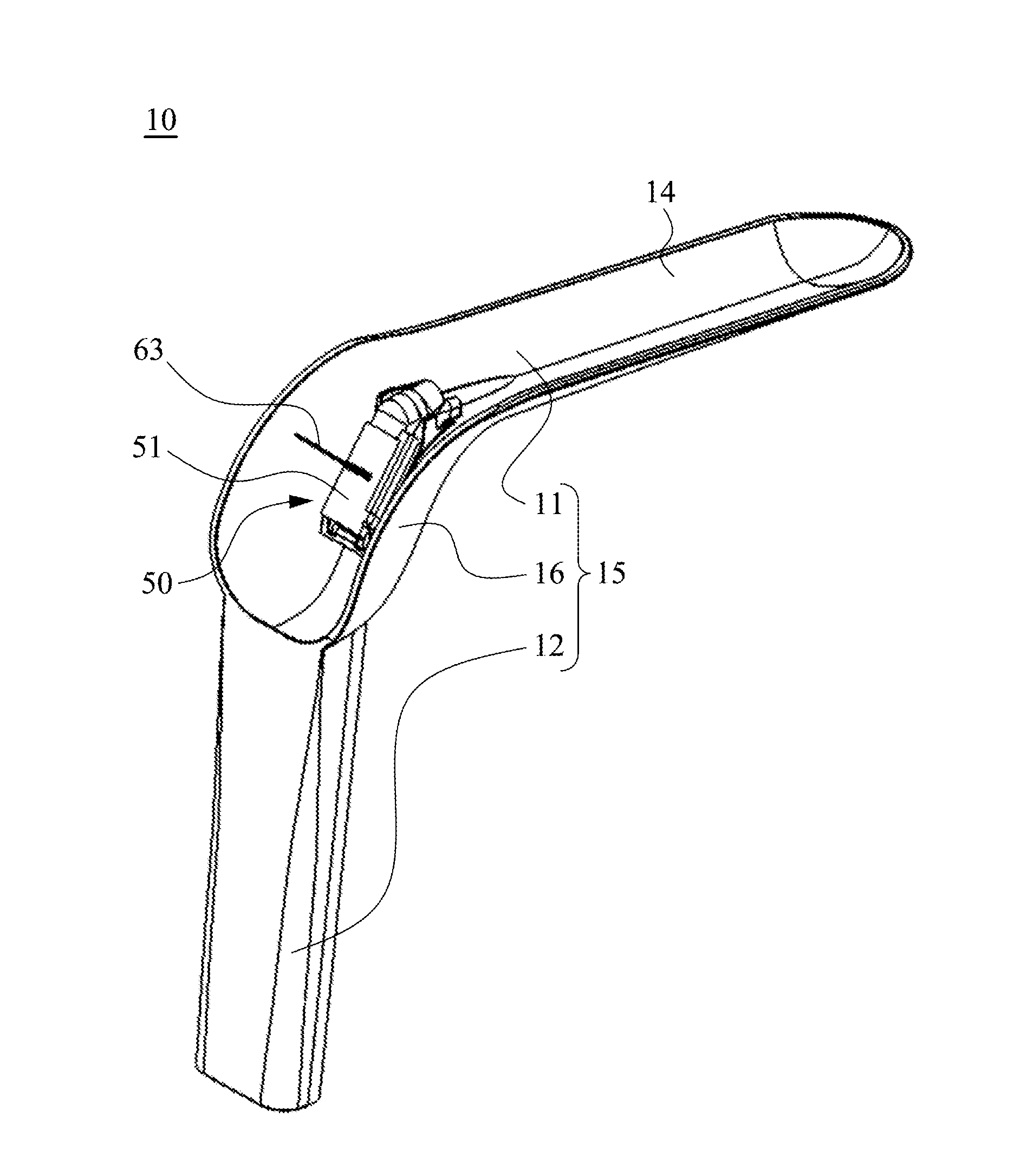
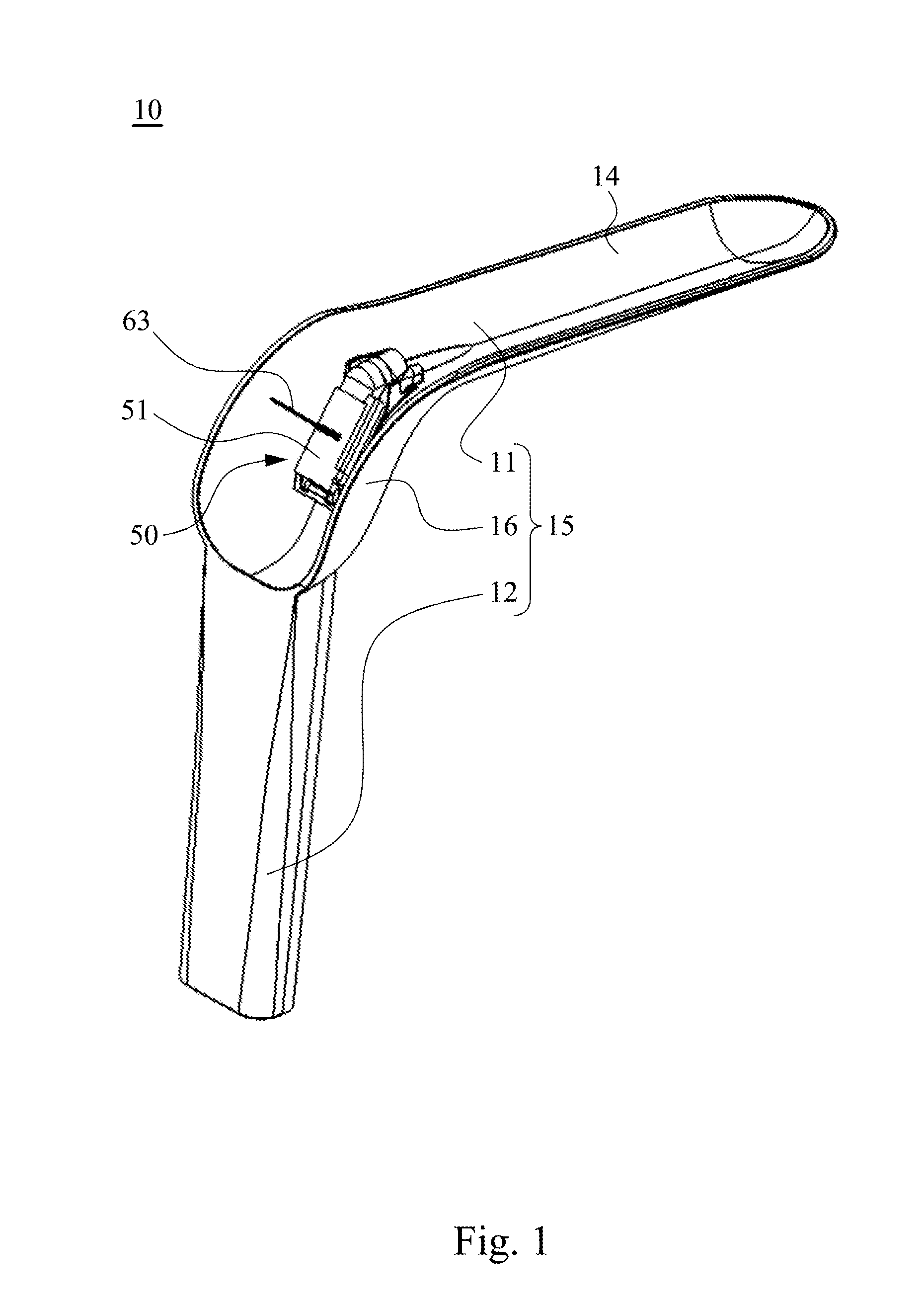
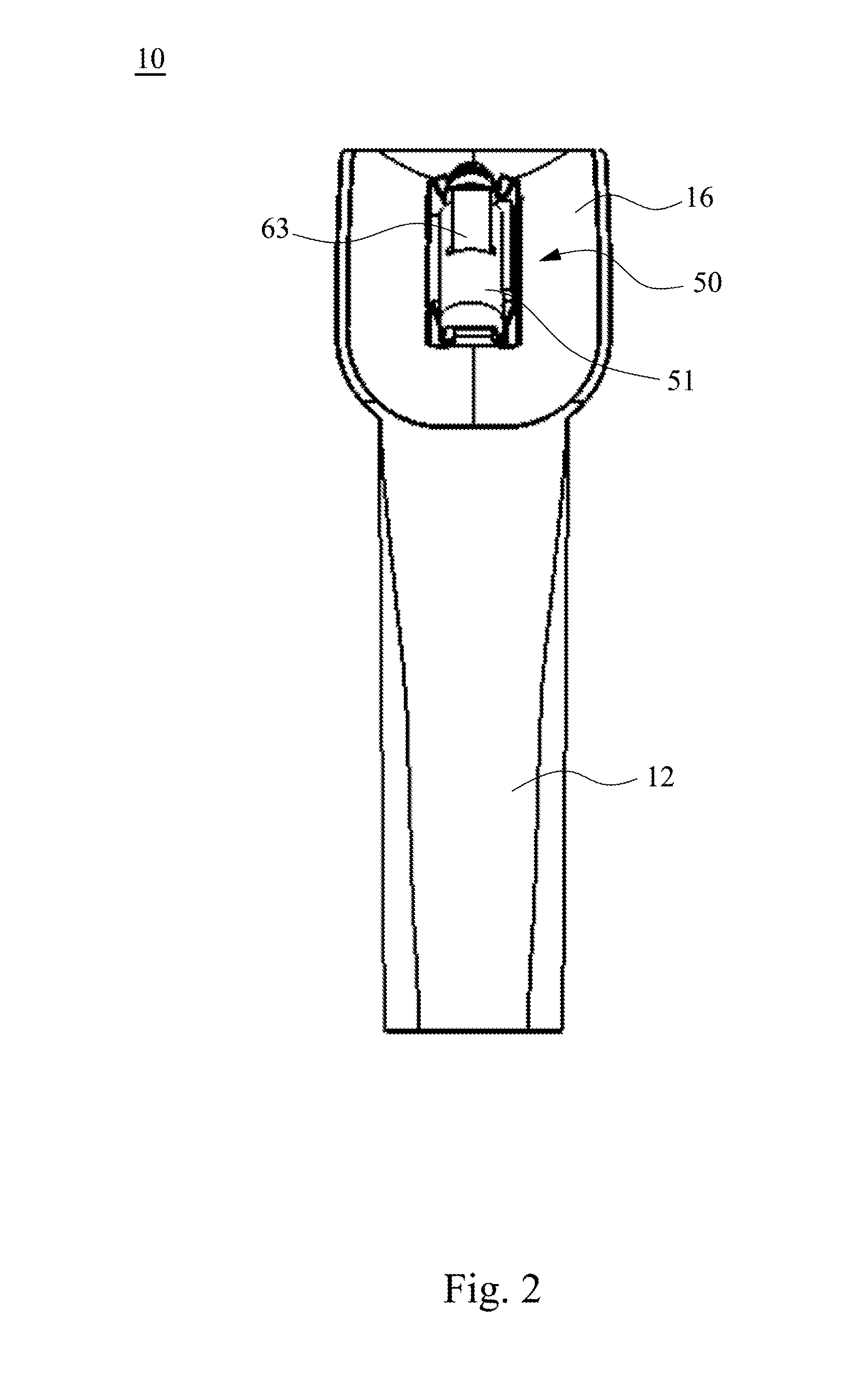
An illuminated surgical retractor includes a blade, a handle, a curved section and an illumination assembly. The blade has a top surface and a bottom surface. The handle extends at an angle from a proximal end of the blade. The curved section connects the handle to the blade. The illumination assembly includes at least one light source, at least one battery and an activation device for energizing the light source. The illumination assembly is attachable to the curved section.

Description

BACKGROUND[0001]1. Technical Field[0002]The present disclosure relates to illuminated surgical retractors.[0003]2. Description of Related Art[0004]Existing technology for illumination during surgical medical procedures includes overhead illumination. This illumination comes from either overhead lighting or head mounted fiber optic systems. Traditional overhead lighting systems face numerous limitations, A direct exposure of the field from the overhead source is required. Changes in patient or surgeon positioning may interfere with the light source. Frequent adjustments provide an inconvenience for the surgeon and disrupt the surgical flow. Overhead lighting is frequently inadequate for surgery in deeper cavities where more intense focused illumination may be required. In addition, the alignment of the surgeon's head frequently interferes with the remote illumination and prevents light from reaching the field. Head mounted fiber optic systems are used frequently for more limited surg...

Claims


Application Information

Patent Timeline
IPC IPC(8): A61B17/02A61B19/00
CPCA61B90/30A61B17/0206A61B2090/309A61B17/02A61B2017/0023A61B2017/00734A61B2017/00477
Inventor SWIFT, JEFFREY RALPH
Owner OBP SURGICAL CORP
Learn More