Epicardial lead design

a technology of epicardial lead and electrode, which is applied in the field of new design of epicardial lead, can solve the problems of invariably failing pacemakers with electrodes on the fetal heart, no effective treatment of fetal heart block, etc., and achieve the effects of reducing the strain on the pacemaker electrode, reducing the risk of electrode dislocation, and reducing the risk of power consumption and interferen

Active Publication Date: 2016-08-11
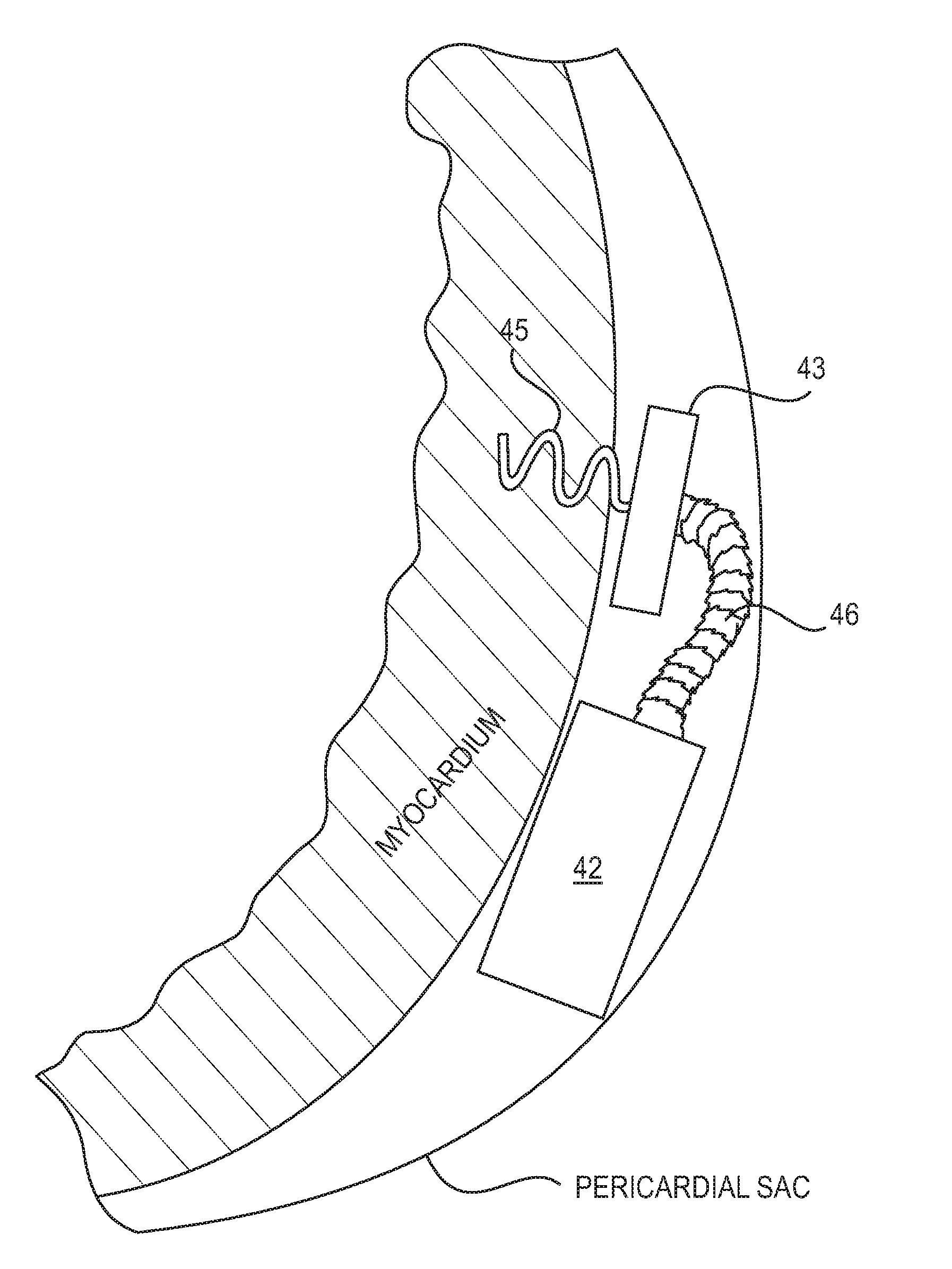
CHILDRENS HOSPITAL OF LOS ANGELES +1
View PDF4 Cites 12 Cited by
  • Summary
  • Abstract
  • Description
  • Claims
  • Application Information

AI Technical Summary

Benefits of technology

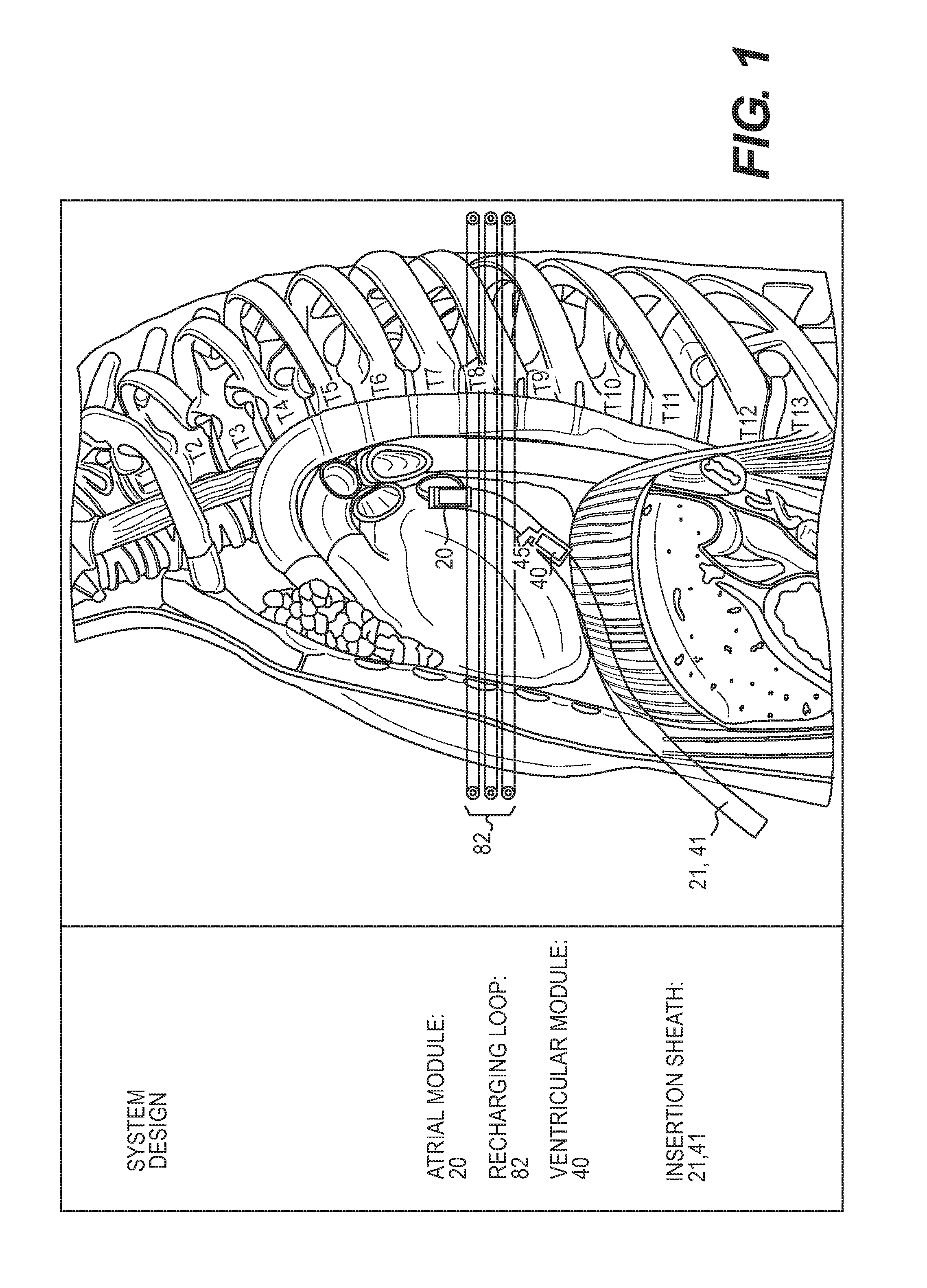
[0013]The present invention provides a novel micropacemaker design, and in particular a pacemaker lead design, to address the critical problem of complete heart block in patients of all sizes, including fetal patients, pediatric patients, and adult patients. Until recently, fetal heart block had no effective treatment except for early delivery because early attempts to implant an extra-uterine pacemaker with electrodes on the fetal heart invariably failed due to lead dislodgement from fetal movement. To address this problem, the present inventors designed a self-contained, single-chamber, rechargeable micropacemaker that can be completely implanted in the fetus without exteriorized leads, allowing for subsequent fetal movement without risk of electrode dislodgement. The present invention advances that concept to provide a percutaneous implantation scheme for micropacemakers and larger epicardial devices that provide demand pacing, variable rates, and a multi-chamber system via a modular configuration, as well as a battery having a life of potentially greater than six months between charges and being capable of being recharged wirelessly, which permits potentially decades of device life. The present invention further advances that concept by providing a lead design that reduces strain on the pacemaker electrode and on the myocardial tissue at the point of insertion of the pacemaker.
[0014]The device

Problems solved by technology

Until recently, fetal heart block had no effective treatment except for early delivery because early attempts to implant an

Method used


Image

  • Epicardial lead design
  • Epicardial lead design
  • Epicardial lead design

Examples


Embodiment Construction

[0024]Reference will now be made in detail to various exemplary embodiments of the invention. It is to be understood that the following discussion of exemplary embodiments is not intended as a limitation on the invention, as broadly disclosed herein. Rather, the following discussion is provided to give the reader a more detailed understanding of certain aspects and features of the invention.

[0025]Before embodiments of the present invention are described in detail, it is to be understood that the terminology used herein is for the purpose of describing particular embodiments only, and is not intended to be limiting. Further, where a range of values is provided, it is understood that each intervening value, to the tenth of the unit of the lower limit, unless the context clearly dictates otherwise, between the upper and lower limits of that range is also specifically disclosed. Each smaller range between any stated value or intervening value in a stated range and any other stated or in...


PUM


Abstract

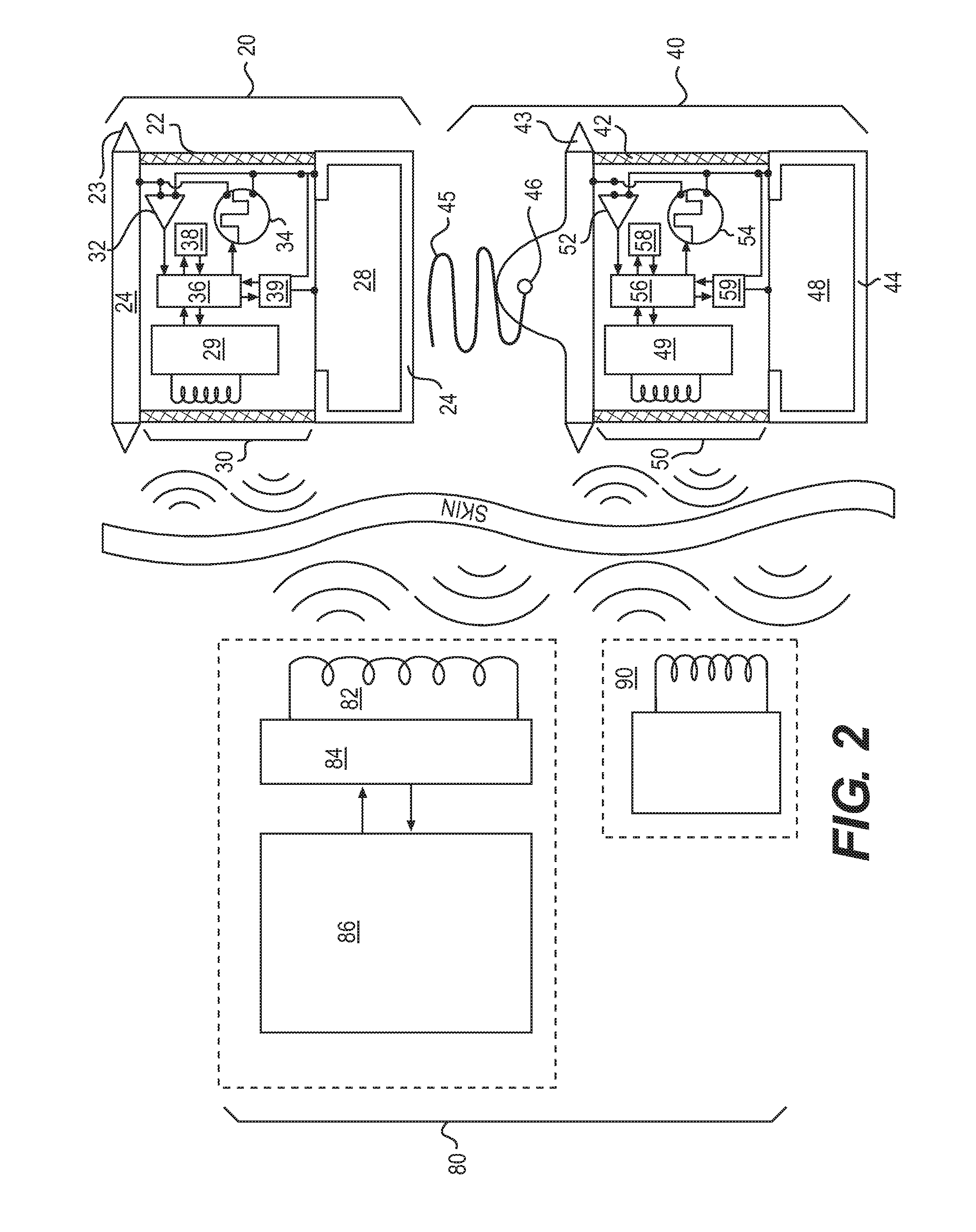
The present invention provides advancements in the art of cardiac pacemakers. The invention provides a pacemaker system that comprises at least one pacemaker and that is, to a large extent, self-controlled, allows for long-term implantation in a patient, and minimizes current inconveniences and problems associated with battery life. The invention further includes a mechanism in which at least two pacemakers are implanted in a patient, and in which the pacemakers communicate with each other at the time of a given pacing or respiratory event, without any required external input, and adjust pacing parameters to respond to the patient's need for blood flow. The invention further provides a design for a pacemaker in which the pacemaker electrode is connected to the pacemaker body by a lead that is configured to allow the pacemaker to lie parallel to the epicardial surface and to reduce stress on the pacemaker and heart tissue.

Description

CROSS-REFERENCE TO RELATED APPLICATIONS[0001]This invention relies on, and claims the benefit of the filing dates of U.S. provisional patent application No. 61 / 820,809, filed 8 May 2013, and U.S. provisional patent application No. 61 / 924,253, filed 7 Jan. 2014, the entire disclosures of both of which are hereby incorporated by reference in their entireties.BACKGROUND OF THE INVENTION[0002]1. Field of the Invention[0003]The present invention relates to the field of medical devices. More specifically, the present invention relates to a new design for an epicardial lead, which allows a pacemaker to lie parallel to the myocardium and pericardial sac with little or no stress on the pacemaker electrode or myocardial tissue.[0004]2. Description of Related Art[0005]Since their introduction in the 1950s, cardiac pacemakers have generally taken the form of a surgically implanted pulse generator powered by a primary cell and connected to one or more flexible leads that pass through the major v...

Claims


Application Information

Patent Timeline
IPC IPC(8): A61N1/375A61N1/378A61N1/372A61N1/05A61N1/362
CPCA61N1/375A61N1/3756A61N1/0587A61N1/37288A61N1/362A61N1/37205A61N1/3787A61N1/059A61N1/37512
Inventor BAR-COHEN, YANIVLOEB, GERALDZHOU, LIPECK, RAYMONDNUTT, STEPHEN
Owner CHILDRENS HOSPITAL OF LOS ANGELES
Why Eureka
Try Eureka