
Method for accurately calibrating discharge volume of pipette, and apparatus therefor

a discharge volume and pipette technology, applied in the field of pipette, can solve the problems of difficult selection of appropriate patterns, inability to use pipette on site, etc., and achieve the effects of simple calibration, easy and accurate calibration, and accurate discharg

Inactive Publication Date: 2016-08-18
A&D CO LTD
View PDF6 Cites 7 Cited by
  • Summary
  • Abstract
  • Description
  • Claims
  • Application Information

AI Technical Summary

Benefits of technology

The present invention provides a method for accurately calibrating the discharge volume of a pipette, chip, and liquid used in a measurement. This is done by calibrating the pipette to match its sucking amount with an amount obtained by multiplying the preset amount by the ratio, or by inputting the actual discharge amount into the pipette to be displayed and calibrated to represent the actual discharge amount. This simplifies the calibration process and ensures accurate discharging with the pipette, chip, and liquid. Additionally, the calibration can be done in a unified unit of weight, making the calibration process easier.

Problems solved by technology

However, in the pipette of the Patent Publication 1, each of different tips, liquids, and environmental conditions are stored, a large number of patterns are generated so that the selection of an appropriate pattern may be difficult.
Furthermore, the pattern that is coincident with the current condition may not exist, then the pipette may not be reasonable to use on the site.

Method used


Image

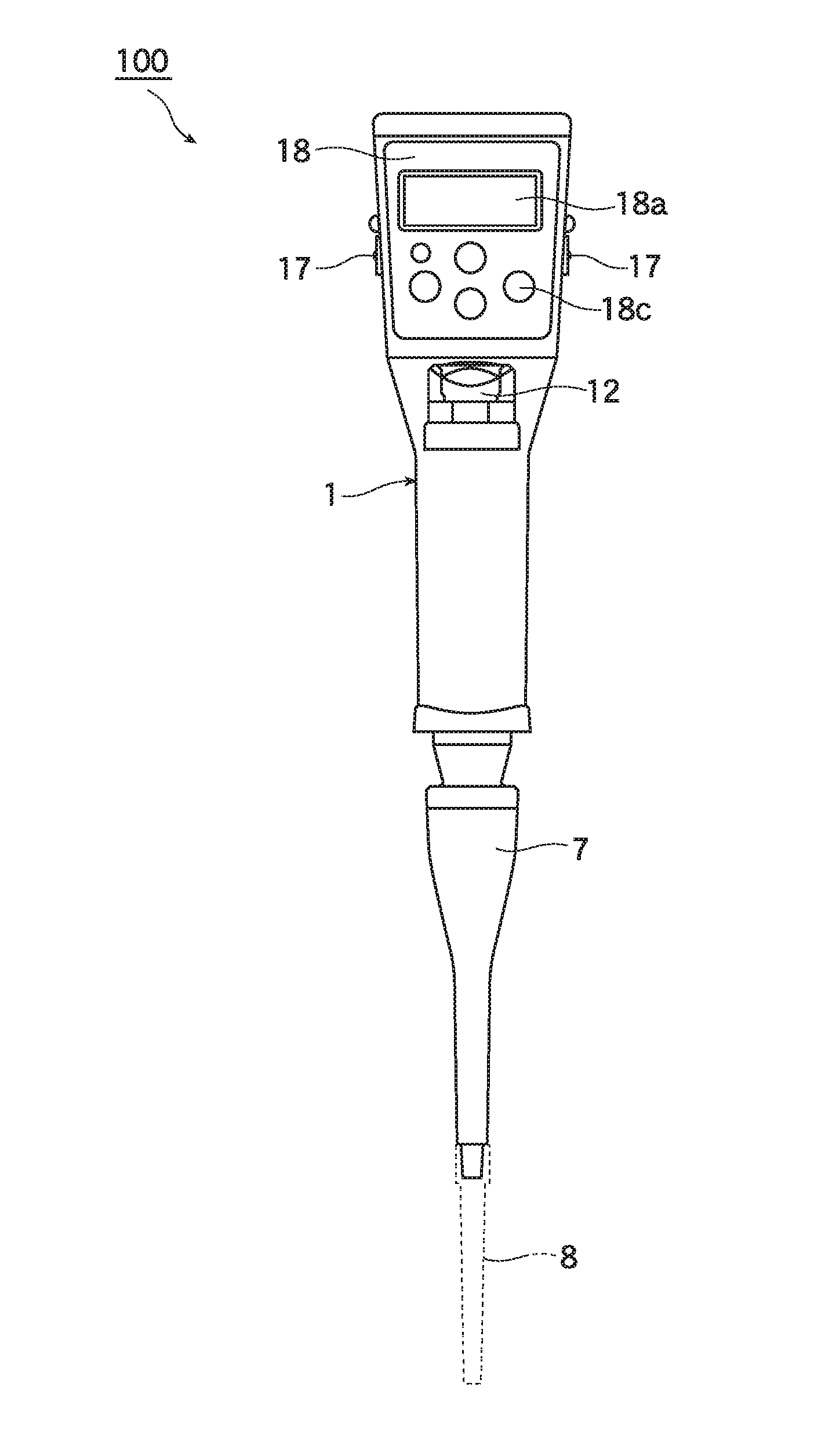
  • Method for accurately calibrating discharge volume of pipette, and apparatus therefor
  • Method for accurately calibrating discharge volume of pipette, and apparatus therefor
  • Method for accurately calibrating discharge volume of pipette, and apparatus therefor

Examples


first embodiment

of the Calibration Method

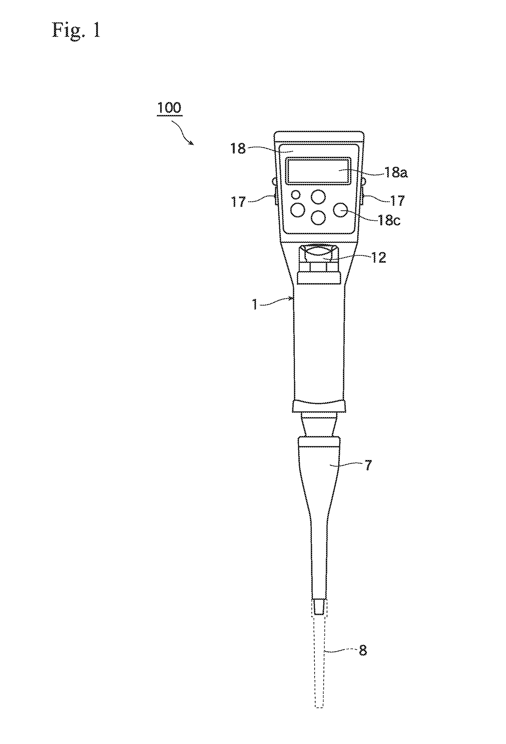
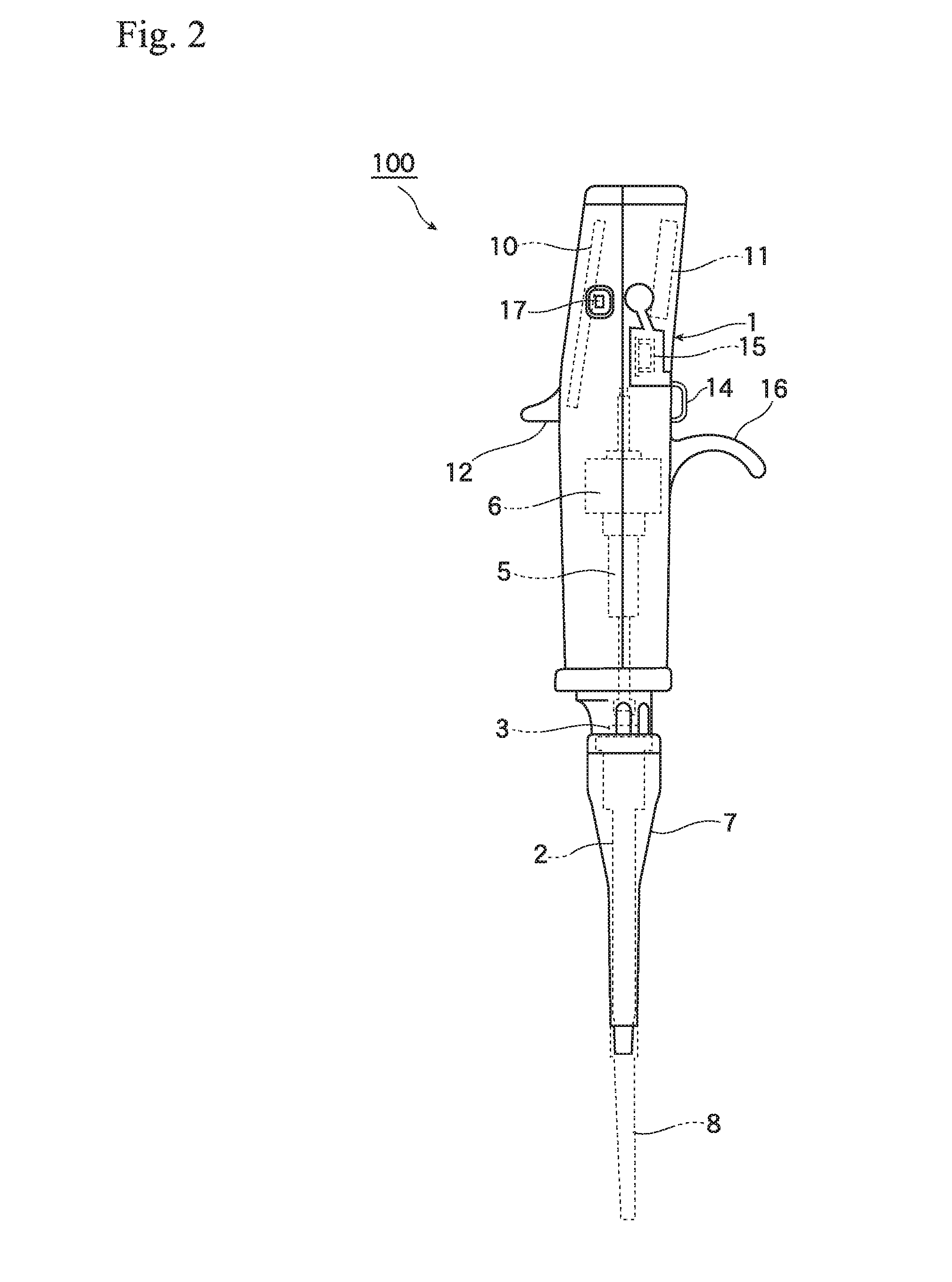
[0035]FIG. 4 is a flow chart regarding a first calibration method of the electric pipette. At a step S0 as an advance step, the pipette 100 and the chip 8 actually used in a measurement are chosen and the liquid actually used in the measurement is prepared.

[0036]When a first calibration mode is chosen, the processing is shifted to a step S1, a preset volume parameter V0 [unit: L / mL / micro L] is set by choosing or inputting from the operation key 18c. The chosen or inputted value is displayed on the display 18a.

[0037]Then, the processing is shifted to a step S2, the liquid is sucked in the chip 8 by pushing the operation switch 14.

[0038]Then, the processing is shifted to a step S3, the liquid is discharged on a weight apparatus which can measure weight of the liquid by pushing the operation switch 14. The resolving power of the weight apparatus is selected with respect to the preset volume. For example, when the pipette is set the preset volume, 20 micro L, r...

second embodiment

of the Calibration Method

[0048]FIG. 5 is a flow chart regarding a second calibration method of the electric pipette. The second calibration method can be performed a simpler calibration than the first calibration method by unifying unit of the preset amount by weight. The description of the steps which are similar to that of the first embodiment are omitted by using the same step number.

[0049]When a second calibration mode is chosen, the processing is shifted to a step S21. The step S21 is similar to the step S1 in the first calibration method. A different point is that the preset amount is performed by weight. In the step S21, the preset amount is set by choosing or inputting of a preset weight “G0” [unit: g / mg / micro g].

[0050]Next, the processing is shifted to steps S22, S23, and S24 and the liquid is sucked in the chip 8 and discharged on the weight apparatus as steps S2, S3, and S4. The measurement weight “G” [unit: g / mg / micro g] is measured and inputted, and an actual discharge ...

third embodiment

of the Calibration Method

[0056]FIG. 6 is a flow chart regarding a third calibration method of the electric pipette. The third calibration method calibrates a displayed amount with respect to the first calibration method which corrects the sucking amount. The description of the steps which are similar to that of the first embodiment are omitted by using the same step number.

[0057]When a third calibration mode is chosen, the processing is shifted to steps S31 to S36. The steps S31 to S36 are similar to the steps S1 to S6.

[0058]Then, the processing is shifted to a step S37, the arithmetic processing device 20 changes the preset volume “V0” displayed in the display 18a to the actual discharge volume “V” obtained in the step S36.

[0059]The processing is shifted to a step S38, the data memory 21 stores information regarding the present calibration, and the calibration is ended.

Forth Embodiment of the Calibration Method

[0060]FIG. 7 is a flow chart regarding a forth calibration method of the...


PUM


Abstract

To provide a method for calibrating a discharge volume of the pipette that enables accurate measurement of the discharge volume under arbitrary conditions, and to provide an apparatus therefor. The method including the steps of, setting a preset volume by the pipette that is actually used in a measurement (S1), sucking liquid that is actually used in the measurement into the pipette chip that is actually used in the measurement while aiming to be sucked the preset volume (S2), discharging the liquid sucked in the pipette chip onto a measuring apparatus (S3), determining an actual discharge volume of the pipette based on the weight measured (S4 to S6) and calculating a ratio between the preset volume and the actual discharge volume and correcting a sucking amount so as to bring the sucking amount to match an amount obtained by multiplying the preset volume by the ratio (S7 to S9).

Description

TECHNICAL FIELD[0001]The present invention relates to a pipette acting as an apparatus for sucking and discharging a preset volume of liquid, and more particularly to a method for accurately calibrating a discharge volume of the pipette and a pipette therefor.BACKGROUND ART[0002]A pipette is well known measurement apparatus, having a function for discharging a constant volume of liquid by detecting a volumetric change of moving of air in the pipette caused by a move of a piston equipped in the pipette. The pipette sucks and discharges a volume of liquid that is equivalent to the volumetric change of the air in a pipette chip attached at the leading end of the pipette. In principles, the compressible air is utilized as a medium, the preset volume is influenced by an error, for example, resistance of the air in the air circuit, operational mode of the piston, configuration of the chip such as its length and the shape of the pointed end thereof, properties of the liquid such as hydroph...

Claims


Application Information

Patent Timeline
Patent Type & Authority Applications(United States)
IPC IPC(8): B01L3/02
CPCB01L3/021B01L2200/148B01L2300/0645G01F25/00B01L2300/0832G01F13/00B01L3/0227B01L3/0237B01L2300/0627G01N1/00G01F25/0084G01G1/00G01G23/01G01F11/022G01F11/023G01F11/027
Inventor IZUMO, NAOTOFUKAMI, YUJI
Owner A&D CO LTD
Learn More