
Robot

a robot and robot technology, applied in the field of robots, to achieve the effect of avoiding contact with the external environmen

Active Publication Date: 2016-08-18
HONDA MOTOR CO LTD
View PDF2 Cites 3 Cited by
  • Summary
  • Abstract
  • Description
  • Claims
  • Application Information

AI Technical Summary

Benefits of technology

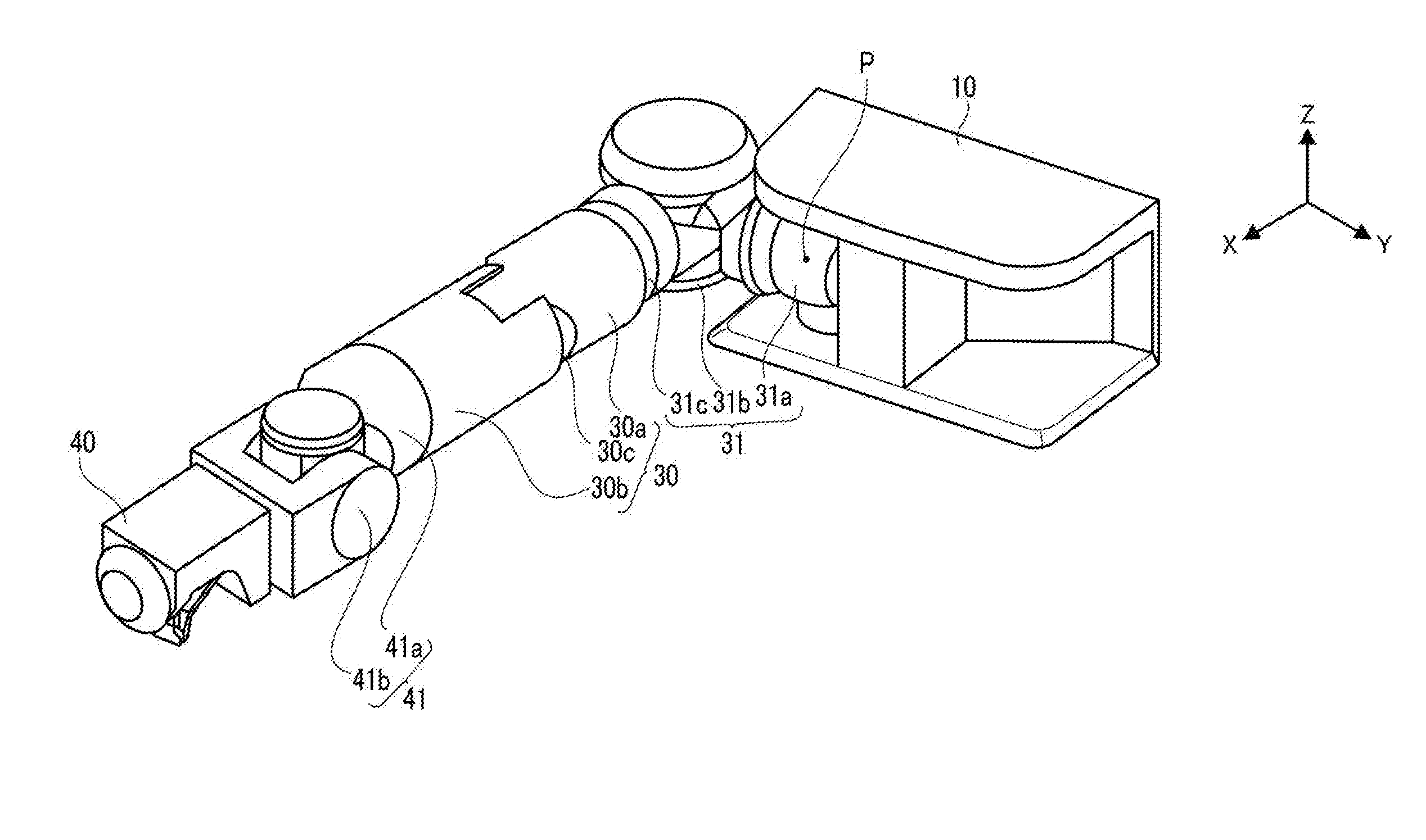
The robot described in this patent is designed to have a compact size and a reduced height and width compared to conventional robots. It achieves this by placing the fulcrum of rotation of the movable link within the range of the widths of the base body in both the vertical and horizontal directions. This setup also allows the joint mechanism to be located within the range of the base body, further reducing the size of the robot. By having a shorter first link part connected to the base body and a longer second link part, the space required for movement of the movable links is minimized, making it easier for the robot to move through narrow passages or go up back basket ladders without interfering with its external environment.

Problems solved by technology

Therefore, in the conventional robot, there has been a problem that when work is performed using end effectors provided at the movable links, or when the robot is moved, a space for work or movement must be set also in consideration of sizes of the joint mechanisms since the sizes of the joint mechanisms in addition to a size of a base body part largely affect the work or movement.

Method used


Image

  • Robot
  • Robot
  • Robot

Examples


Embodiment Construction

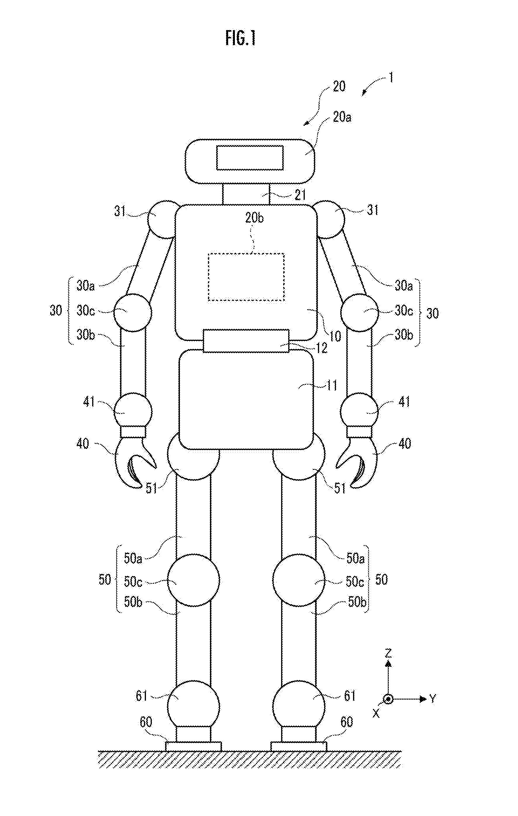
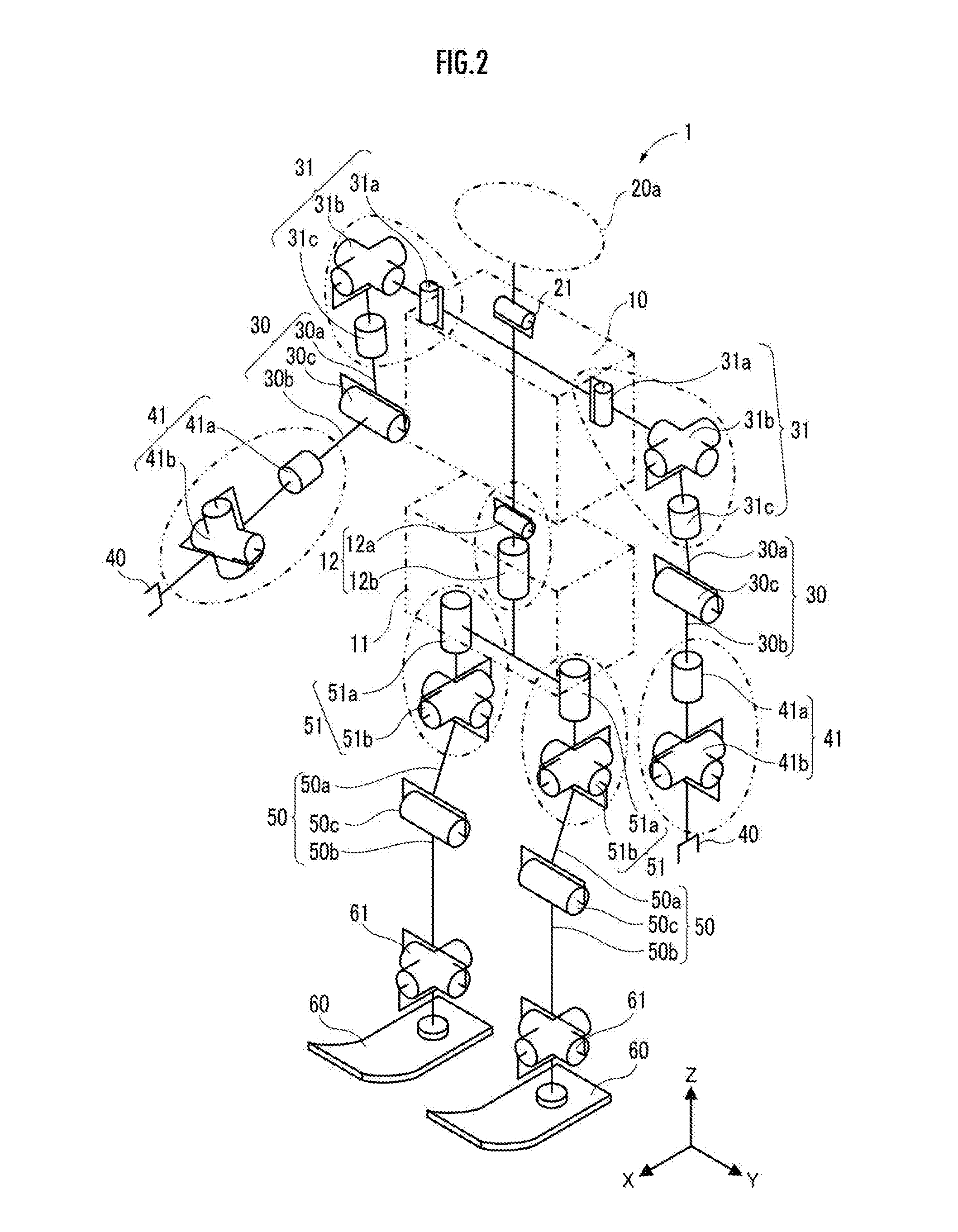
[0038]Hereinafter, an embodiment of a robot according to the present invention will be explained with reference to drawings. A robot 1 of the embodiment is a humanoid, and is configured to be able to move while switching between a bipedal walking mode and a quadrupedal walking mode.

[0039]However, the robot in the present invention is not limited to the humanoid configured as described above, but robots each having a mode different from the robot 1 of the embodiment are also included if they are robots comprising: a base body; a joint mechanism; and a movable link coupled to the base body through the joint mechanism, such as other industrial robots.

[0040]First, a configuration of the robot 1 of the embodiment will be explained with reference to FIG. 1.

[0041]A body of the robot 1 includes: an upper base body 10; a lower base body 11 arranged below the upper base body 10; and a waist joint mechanism 12 provided between the upper base body 10 and the lower base body 11. The upper base b...


PUM


Abstract

An arm link (30) is rotatably coupled to an upper base body (10) around a yaw axis through a shoulder joint mechanism (31). A fulcrum P of rotation of the arm link (30) is located within a range of widths of the upper base body (10) in a vertical direction and a horizontal direction of the upper base body (10).

Description

BACKGROUND OF THE INVENTION[0001]1. Field of the Invention[0002]The present invention relates to a robot comprising a movable link extended from a base body through a joint mechanism.[0003]2. Description of the Related Art[0004]Conventionally, there is a robot which performs various works by an end effector of a movable link coupled to a base body through a joint mechanism.[0005]As this kind of robot, similarly to human beings, there has been known a robot comprising: a base body as a body; a head provided above the base body; right and left arm bodies extended from upper right and left sides of the base body; hands attached to end parts of the arm bodies; right and left leg bodies extended downwardly from a lower part of the base body; and foot flat parts attached to end parts of the leg bodies (for example, refer to Japanese Patent No. 4774964).[0006]The robot described in Japanese Patent No. 4774964 can bend and stretch movable links, such as the arm bodies and the leg bodies in ...

Claims


Application Information

Patent Timeline
Patent Type & Authority Applications(United States)
IPC IPC(8): B25J17/00B25J18/04
CPCB25J17/00Y10S901/28B25J18/04B62D57/032
Inventor WAITA, HIRONORIMIYAZAKI, SUSUMUYOSHIIKE, TAKAHIDEUJINO, RYUMAKANAZAWA, MASAO
Owner HONDA MOTOR CO LTD
Learn More