

Control apparatus for vehicle
- Summary
- Abstract
- Description
- Claims
- Application Information
AI Technical Summary
Benefits of technology
Problems solved by technology
Method used
Image

Examples
Embodiment Construction
[0021]The embodiment of the invention will be described hereinafter in detail with reference to the drawings.
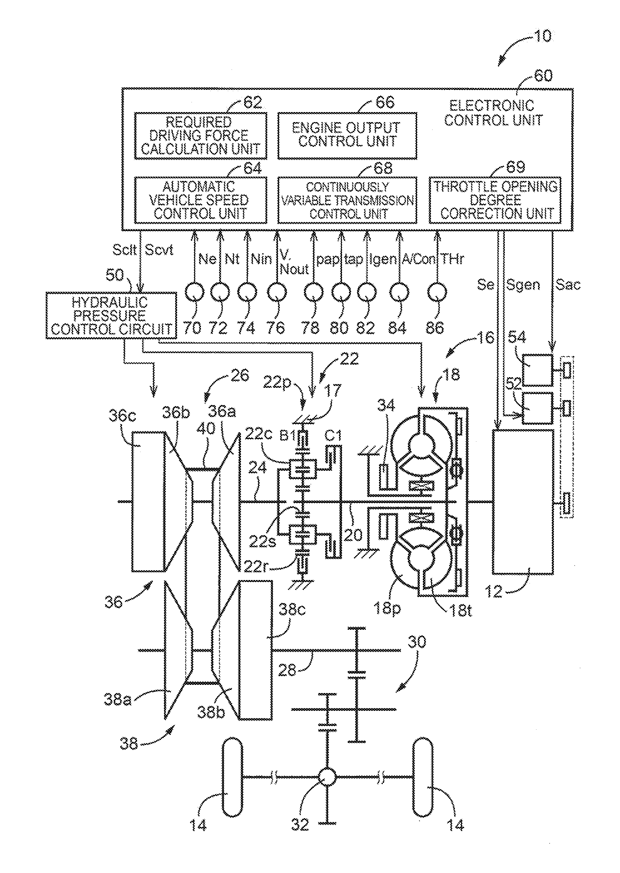
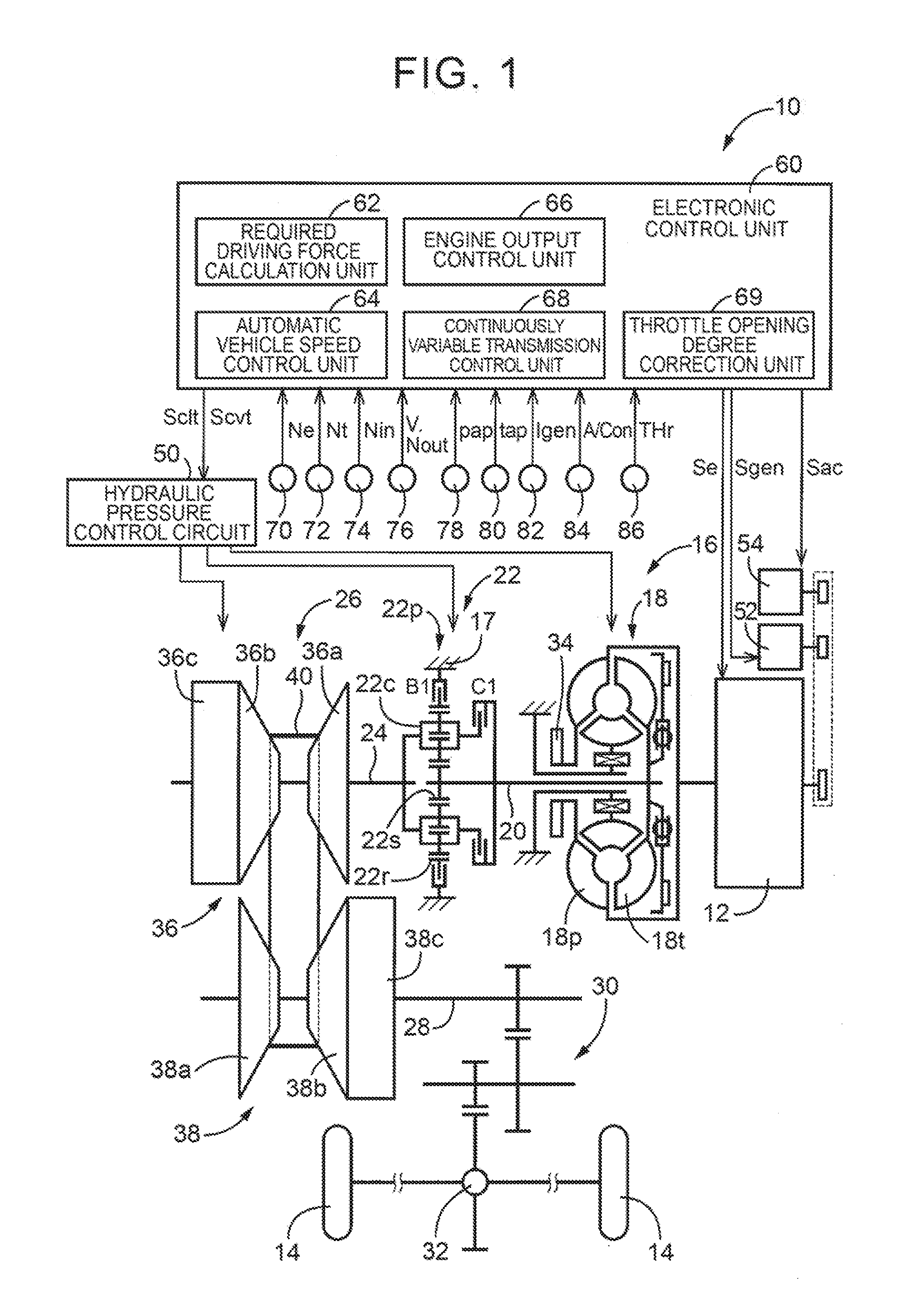
[0022]FIG. 1 is a view illustrating the general configuration of a vehicle 10 to which the invention is applied, and is a view illustrating the essence of control functions and control systems for various kinds of control in the vehicle 10. In FIG. 1, the vehicle 10 is equipped with an engine 12 as a driving force source for running, driving wheels 14, and a motive power transmission device 16 that is provided between the engine 12 and the driving wheels 14. In a housing 17 as a non-rotary member, the motive power transmission device 16 is equipped with a known torque converter 18 as a hydraulic power transmission that is coupled to the engine 12, a turbine shaft 20 that is coupled to the torque converter 18, a forward / backward changeover device 22 that is coupled to the turbine shaft 20, an input shaft 24 that is coupled to the forward / backward changeover device 22, a contin...
PUM
 Abstract
Description
Claims
Application Information