Check patentability & draft patents in minutes with Patsnap Eureka AI!

Object detection apparatus and object detection system

a technology of object detection and object detection, applied in the direction of reradiation, electromagnetic wave detection, instruments, etc., can solve the problems of reducing the detection performance of objects, high cost, etc., and achieve the effect of suppressing the detection performance decrease, reducing the cost of calculating the object determination threshold, and low apparent frequency

Active Publication Date: 2016-08-18
DENSO CORP
View PDF14 Cites 7 Cited by
  • Summary
  • Abstract
  • Description
  • Claims
  • Application Information

AI Technical Summary

Benefits of technology

The present invention aims to provide an object detection apparatus and system that can suppress the influence of road surface reflection noise on object detection while suppressing cost increase and detection performance decrease. The apparatus and system utilize a reflected wave from a road surface that is filtered to identify a threshold that is adapted to the road surface condition to distinguish between an object and the noise resulting from the road surface. This approach eliminates the need for a camera to capture the road surface image, reducing cost and improving detection performance. The technical effect of this invention is improved object detection in the presence of road surface reflection noise.

Problems solved by technology

However, the technology disclosed in Patent Literature 1 requires a camera for imaging a road surface, which leads to high cost.
This requires a large margin relative to an appropriate threshold and reduces object detection performance.

Method used


Image

  • Object detection apparatus and object detection system
  • Object detection apparatus and object detection system
  • Object detection apparatus and object detection system

Examples


first embodiment

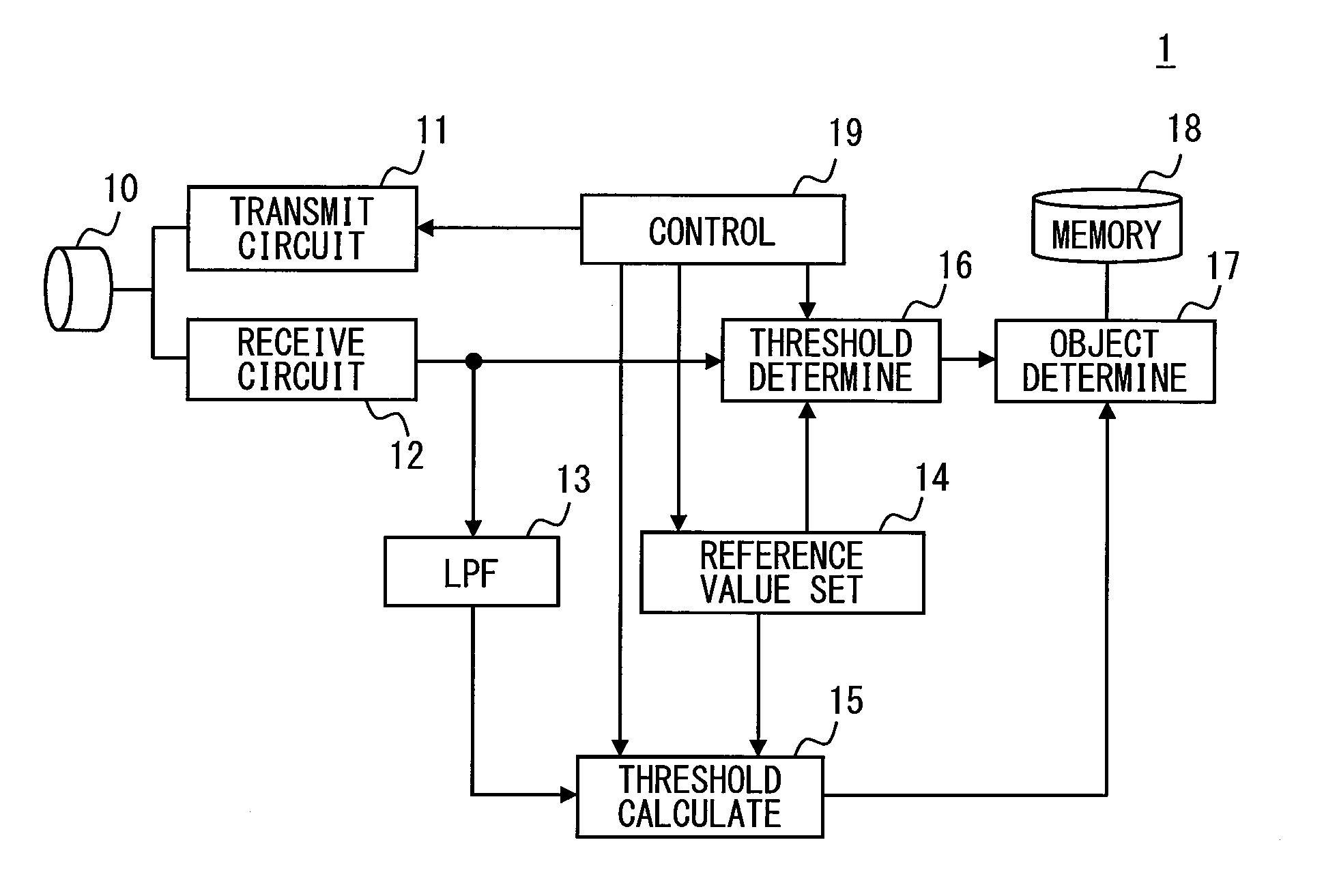
[0021]FIG. 1 is a block diagram illustrating a schematic configuration of an object detection apparatus 1 according to a first embodiment. The object detection apparatus 1 illustrated in FIG. 1 is mounted to a vehicle and detects an object that could be an obstacle of the vehicle. As shown in FIG. 1, the object detection apparatus 1 includes a transceiver 10, a transmitting circuit 11, a receiving circuit 12, a low pass filter (LPF) 13, a reference value setting part 14, a threshold calculation part 15, a threshold determination part 16, an object determination part 17, a memory 18, and a controller 19.

[0022]The transmitting circuit 11 transmits the probe wave in pulse form with the transceiver 10 in accordance with instructions from the controller 19. For example, the transmitting circuit 11 oscillates the transceiver 10 sixteen times at 40 kHz, thereby forming a single pulse. The transmitting circuit 11 corresponds to an example of transmitter. Via the transceiver 10, the receivin...

second embodiment

[0051]Although the first embodiment has been illustrated above, embodiments of the present disclosure are not limited to the first embodiment. The following second embodiment is in embodiments of the present disclosure. In the below, the second embodiment will be illustrated with reference to the drawings. For descriptive purpose, parts having the same functions as those illustrated in the first embodiment and the drawings are assigned the same references and explanations on these are omitted.

[0052]An object detection apparatus 1a of the second embodiment is similar to the object detection apparatus 1 of the first embodiment, except that that the object detection apparatus 1a includes a noise superimposition determination part 20 and the processing of the object determination part 17 differs in part.

[0053]As shown in FIG. 5, the object detection apparatus la includes a transceiver 10, a transmitting circuit 11, a receiving circuit 12, a LPF 13, a reference value setting part 14, a t...

third embodiment

[0061]Although the first and second embodiments have been illustrated above, embodiments of the present disclosure are not limited to the first and second embodiments. The following third embodiment is in embodiments of the present disclosure. In the below, the third embodiment will be illustrated with reference to the drawings. For descriptive purpose, parts having the same functions as those illustrated in the first and second embodiments and the drawings are assigned the same references and explanations on these are omitted.

[0062]An object detection apparatus 1b of the third embodiment is similar to the object detection apparatus 1 of the first embodiment, except that that the object detection apparatus lb includes a down sampling part 22 and a moving average part 23. In the third embodiment, a configuration of the first embodiment that uses the output of the LPF 13 is replaced with a configuration that uses an output after the down sampling part 22 and the moving average part 23...


PUM


Abstract

An object detection apparatus mounted to a vehicle includes a transmitter, a receiver, a filter, a threshold calculator, and an object determinator. The transmitter transmits a probe wave in pulse form. The receiver receives a reflected wave of the probe wave. The filter passes, among the received reflected wave, only frequencies that are at least smaller than a pulse frequency of the probe wave. Based on an output of the filter, the threshold calculator calculates an objection determination threshold for determining presence and absence of an object. The object determinator determines the presence and absence of the object by using the objection determination threshold calculated by the threshold calculator.

Description

CROSS REFERENCE TO RELATED APPLICATION[0001]This application is based on Japanese Patent Application No. 2013-192176 filed on Sep. 17, 2013, the disclosure of which is incorporated herein by reference.TECHNICAL FIELD[0002]The present disclosure relates to an object detection apparatus and an object detection system for detecting an object.BACKGROUND ART[0003]A known object detection apparatus transmits and receives pulse probe wave such as ultrasonic wave and electromagnetic wave to detect an object existing in a probe wave illumination range. Because of directionality of the probe wave, when the probe wave is transmitted in a horizontal direction, the received reflected wave may contain noise resulting from road surface reflection.[0004]A technology for addressing this problem is disclosed in, for example, Patent Literature 1. The technology is provided with an onboard camera for imaging a road surface and determines a threshold for noise removal in accordance with a road surface c...

Claims


Application Information

Patent Timeline
Patent Type & Authority Applications(United States)
IPC IPC(8): G01S7/527G01S15/04G01S15/93G01S15/931
CPCG01V3/12G01S15/931G01S7/52004G01S7/5276G01S7/539G01S15/876G01S15/04G01S2007/52012B60W30/08B60W40/02G01V1/00G01V3/02G08G1/16G01S2013/9353G01S7/52001G01V1/001G01S2013/932
Inventor MATSUURA, MITSUYASUAKIYAMA, KEIKO
Owner DENSO CORP
Features
  • R&D
  • Intellectual Property
  • Life Sciences
  • Materials
  • Tech Scout
  • Unparalleled Data Quality
  • Higher Quality Content
  • 60% Fewer Hallucinations
Learn More