Charge pump having ac and DC outputs for touch panel bootstrapping and substrate biasing

a charge pump and substrate technology, applied in the field of touch sensor panels, can solve problems such as malfunctioning components of the driver i

Active Publication Date: 2016-08-18
APPLE INC
View PDF4 Cites 21 Cited by
  • Summary
  • Abstract
  • Description
  • Claims
  • Application Information

AI Technical Summary

Benefits of technology

[0005]Some capacitive touch sensor panels can be formed by a matrix of substantially transparent or non-transparent conductive plates made of materials such as Indium Tin Oxide (ITO), and some touch screens can be formed by at least partially integrating touch sensing circuitry into a display pixel stackup (i.e., the stacked material layers forming the display pixels). In some examples, one or more components (e.g., a gate line) of the display pixel stackups can be biased by a charge pump on a driver integrated circuit (IC). The charge pump can also provide a bias voltage to a driver IC substrate (i.e., a substrate on which the driver IC can be formed). In some examples, the one or more components of the display pixel stackups may require AC biasing, whereas the driver IC substrate may require DC biasing—in such examples, AC biasing of the driver IC substrate may cause various components on the driver IC to malfunction. The examples of the disclosure are directed to various charge pump configurations that can provide AC or DC biasing of the one or more components of the display pixel stackups, depending on an operational mode of the touch screen, while concurrently providing DC biasing of the driver IC substrate. In some examples, this can be accomplished by providing a charge pump that has separate AC and DC output nodes.

Problems solved by technology

In some examples, the one or more components of the display pixel stackups may require AC biasing, whereas the driver IC substrate may require DC biasing—in such examples, AC biasing of the driver IC substrate may cause various components on the driver IC to malfunction.

Method used


Image

  • Charge pump having ac and DC outputs for touch panel bootstrapping and substrate biasing
  • Charge pump having ac and DC outputs for touch panel bootstrapping and substrate biasing
  • Charge pump having ac and DC outputs for touch panel bootstrapping and substrate biasing

Examples


Embodiment Construction

[0017]In the following description of examples, reference is made to the accompanying drawings that form a part hereof, and in which it is shown by way of illustration specific examples that can be practiced. It is to be understood that other examples can be used and structural changes can be made without departing from the scope of the disclosed examples.

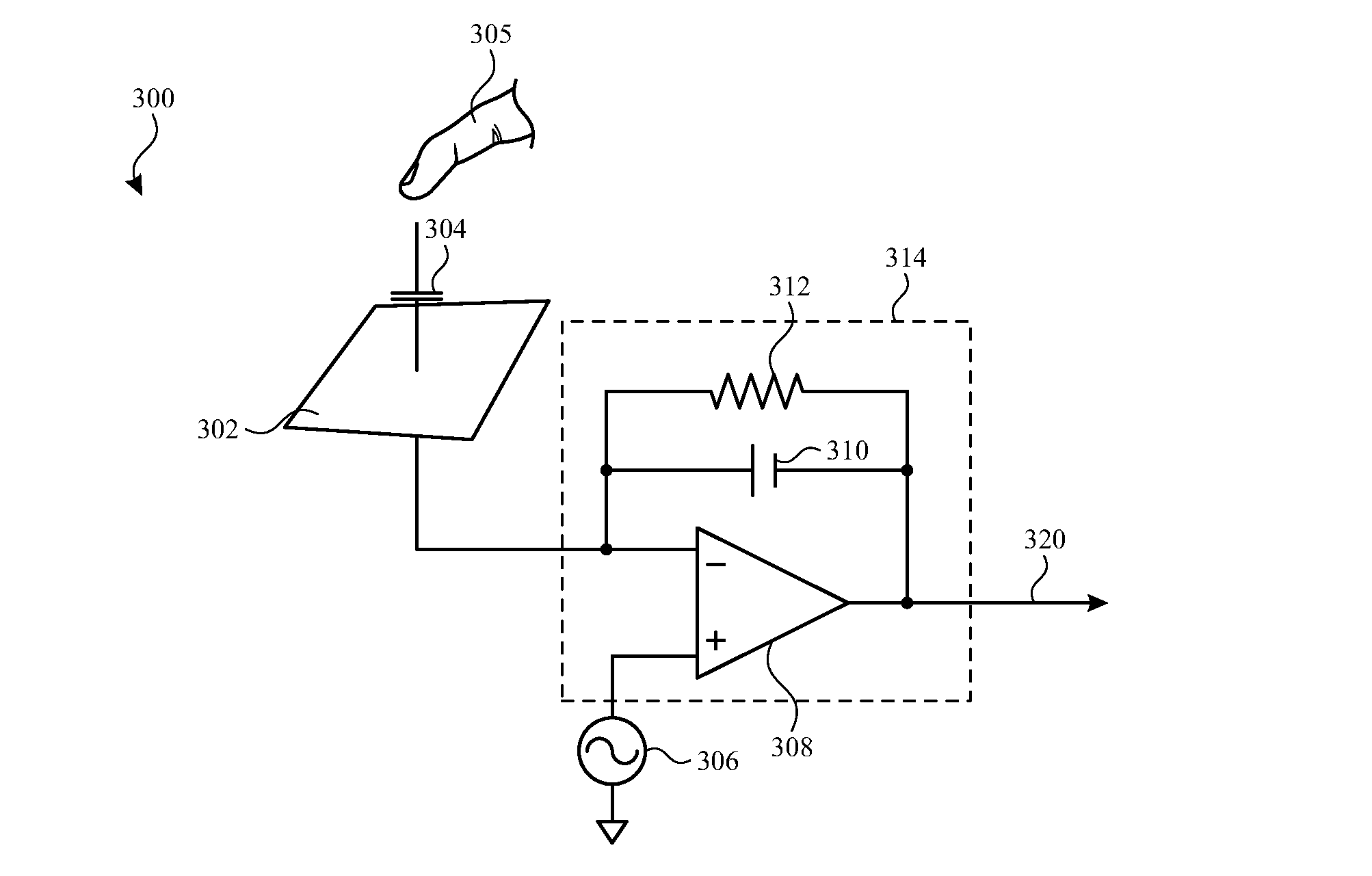
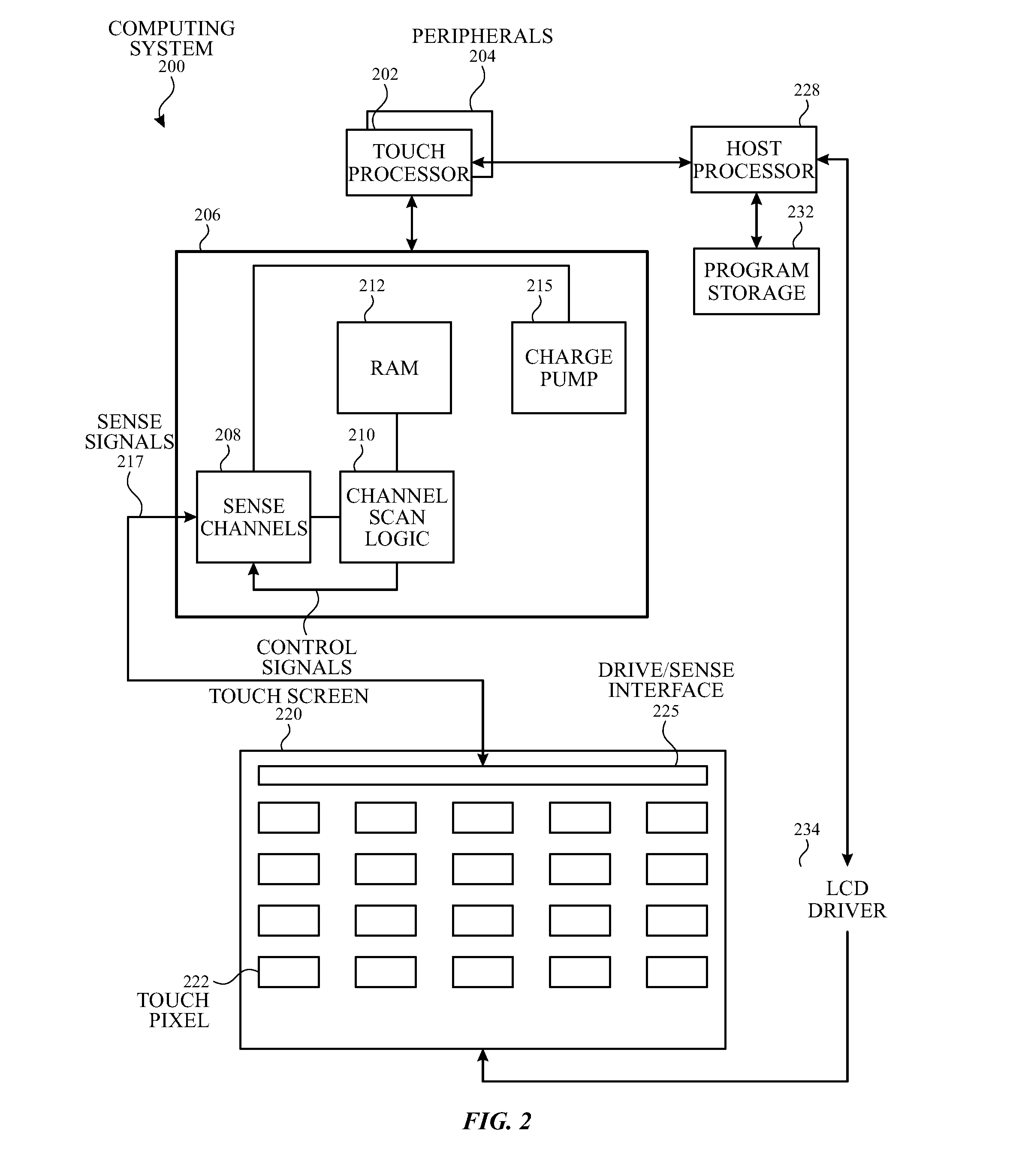
[0018]Some capacitive touch sensor panels can be formed by a matrix of substantially transparent or non-transparent conductive plates made of materials such as Indium Tin Oxide (ITO), and some touch screens can be formed by at least partially integrating touch sensing circuitry into a display pixel stackup (i.e., the stacked material layers forming the display pixels). In some examples, one or more components (e.g., a gate line) of the display pixel stackups can be biased by a charge pump on a driver integrated circuit (IC). The charge pump can also provide a bias voltage to a driver IC substrate (i.e., a substrate on which the dri...


PUM


Abstract

A charge pump that can be configured to operate in a first mode and a second mode is disclosed. The charge pump can comprise a charging capacitor coupled to a first node and configured to transfer a first DC voltage to the first node. The charge pump can also comprise a first output node and a second output node coupled to the first node. During the first mode, the first output node can be configured to output a second DC voltage based on the first DC voltage, and the second output node can be configured to output a third DC voltage based on the first DC voltage. During the second mode, the first output node can be configured to output the second DC voltage, and the second output node can be configured to output an AC voltage, the AC voltage being offset by the third DC voltage.

Description

CROSS-REFERENCE TO RELATED APPLICATIONS[0001]This application claims priority to U.S. Provisional Application No. 62 / 116,178, filed Feb. 13, 2015, which is hereby incorporated by reference in its entirety for all purposes.FIELD OF THE DISCLOSURE[0002]This relates generally to touch sensor panels, and more particularly, to a charge pump for a touch sensor panel or touch screen that has AC and DC outputs that can be used for bootstrapping the touch sensor panel or touch screen, and biasing a driver IC substrate.BACKGROUND OF THE DISCLOSURE[0003]Many types of input devices are presently available for performing operations in a computing system, such as buttons or keys, mice, trackballs, joysticks, touch sensor panels, touch screens and the like. Touch screens, in particular, are becoming increasingly popular because of their ease and versatility of operation as well as their declining price. Touch screens can include a touch sensor panel, which can be a clear panel with a touch-sensiti...

Claims


Application Information

Patent Timeline
Patent Type & Authority Applications(United States)
IPC IPC(8): H02M3/07G06F3/044G06F3/041
CPCG06F1/3262G06F3/041H01L23/642G06F3/044G06F3/0416G06F3/0412H02M3/07G06F3/04166G06F3/0443
Inventor YAO, WEIJUNSTRONKS, DAVID A.BAE, HOPILBRAHMA, KINGSUKYAO, WEI HSINBI, YAFEILI, YINGXUAN
Owner APPLE INC
Why Eureka
Try Eureka