High speed communication for vehicles

a high-speed communication and vehicle technology, applied in the field of cellular communication network network network entity, can solve the problems of high data rate service provision, high speed service provisioning for mobile terminals, and increased compensation difficulty, so as to increase the aggregate data rate, increase the throughput, and reduce the likelihood of outage

Active Publication Date: 2016-08-18
VODAFONE IP LICENSING
View PDF5 Cites 36 Cited by
  • Summary
  • Abstract
  • Description
  • Claims
  • Application Information

AI Technical Summary

Benefits of technology

[0015]The use of a predicted location for the mobile terminal in order to configure a single access node for communication with the mobile terminal is known. For example, EP-2 555 569 A1 and US-2013 / 0005374 use a predicted location for the mobile terminal to provide cross-layer optimisation, more efficient resource allocation and improved data rate. Location prediction is especially useful with regard to moving (that is, non-stationary) mobile terminals, such as vehicles. The predicted location may be based on an indication of location and / or movement data for the first mobile terminal, as will be detailed below. As discussed above, coordinated (such as cooperative) communication using multiple access nodes is also known for static or low-speed mobile terminals. It has now been recognised that the combination of these two techniques provides a synergy that significantly improves the data rate that can be achieved for mobile terminals travelling at high velocities.
[0047]The transmission parameters may relate to one or more different aspects of the wireless link. A first example concerns transmission scheduling. In embodiments, the step of configuring the mobile terminal and / or at least one of the plurality of access nodes further comprises determining that the first and second communications systems are being serviced by the single access node. Then, the step of jointly determining the first and second transmission parameters may comprise identifying a strategy for jointly scheduling transmissions over the first wireless link and over the second wireless link. By scheduling the transmissions together, the use of the access node's resources may be improved and made more efficient.

Problems solved by technology

It is well known that, as the velocity of the mobile terminal increases, problems arise in providing high data rate services.
A number of problems exist in providing services to mobile terminals at high velocity.
Compensation can become more difficult when the velocity increases though.
A second problem relates to channel estimation both at the transmitter and the receiver in both uplink and downlink.
Current channel estimation techniques can provide robust channel estimation at low speed, but use for high speed mobile terminals results in a coarse channel estimation.
As the mobile terminal moves, the channel changes such that previous channel estimations may no longer be valid and cannot be used in a reliable way.
This problem clearly increases as the mobile terminal's velocity gets higher and further limits the data rate that can be provided.
The cellular nature of the network provides a third problem.
This places further strain on the network, increasing overheads and making it more difficult for a high data rate service to be provided.
Another, fourth problem relates to the mechanisms by which signalling is effected in existing cellular communications networks.
When the mobile terminal is travelling at a high velocity, this feedback may not provide any improvement and indeed, may actually degrade the data rate provided.
This is because the feedback may be inaccurate or void of any practical value as it relates to a situation that has changed, due to the movement of the mobile terminal.
Transmitting video adds further problems.
OFDM-based technologies can suffer from high Doppler impact, since the shifting and widening of each subcarrier can reduce orthogonality between them and increase inter-carrier interference.
The possibility of more than one 1000 mobile terminals needing to be serviced across the train is not inconceivable.
This can mean that the uplink transmissions from the two mobile terminals will cause interference towards one another.
Its use when the mobile terminal is travelling at a high velocity is not envisaged, partly because the requirement for feedback cannot readily be met.
At high mobile velocities, the channel estimation requirements to use MIMO are problematic.
In view of the above, meeting the demand for high data rates when the mobile terminal is at high velocity is a significant challenge.

Method used


Image

  • High speed communication for vehicles
  • High speed communication for vehicles
  • High speed communication for vehicles

Examples


first embodiment

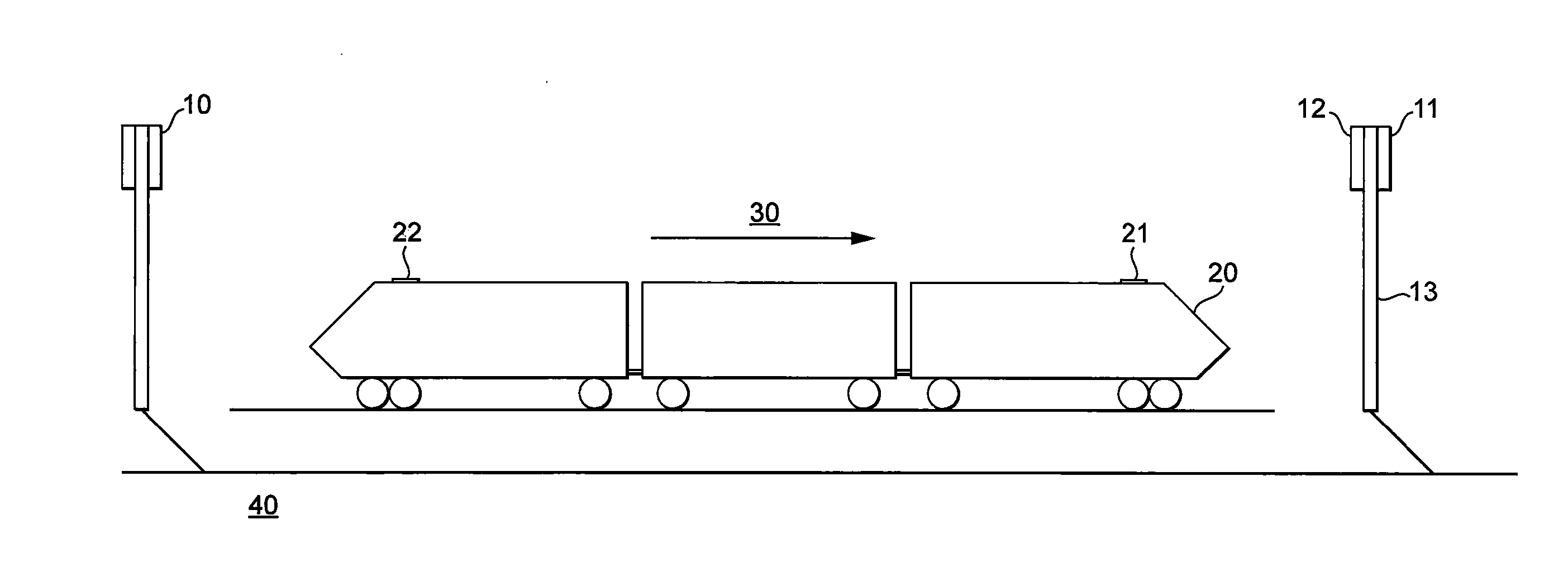
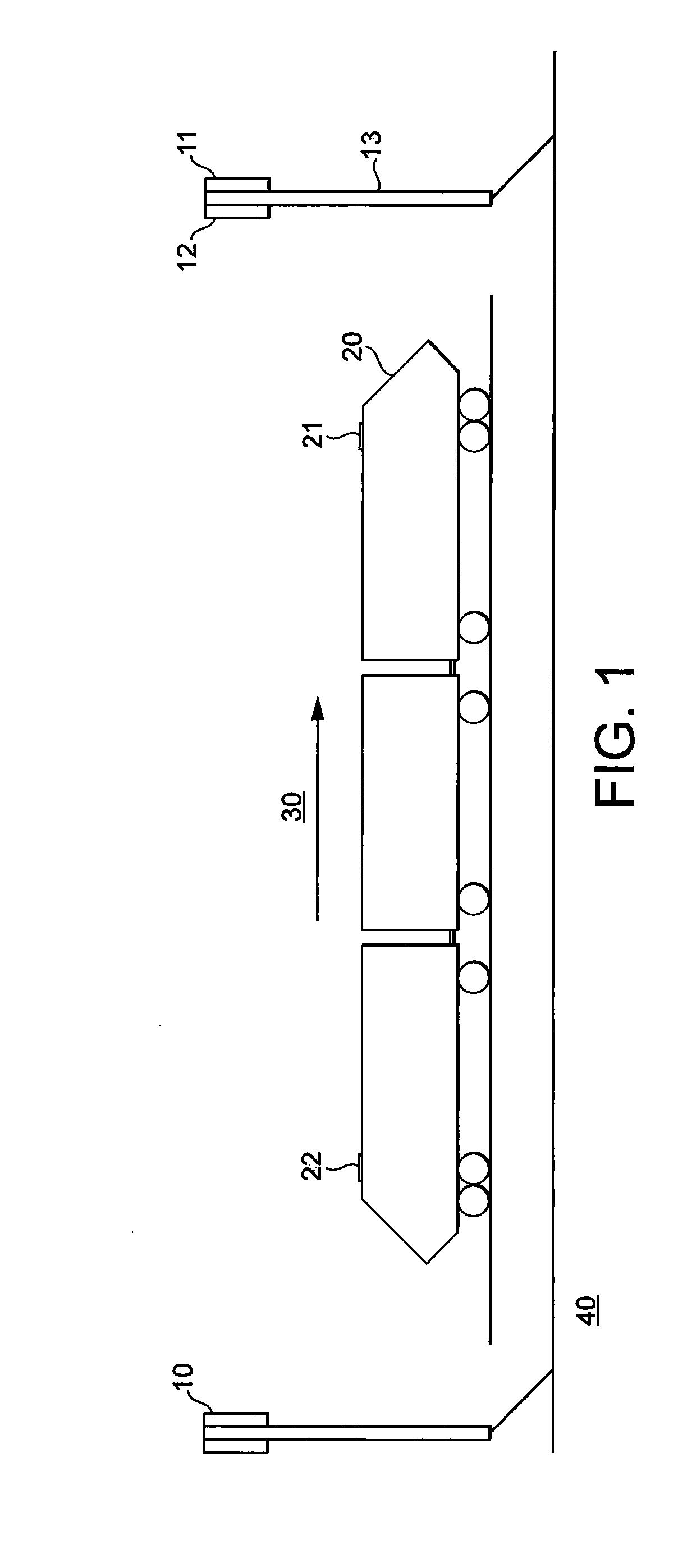
[0071]Referring first to FIG. 1, there is shown a schematic diagram of a system in accordance with the invention. This embodiment relates to a train service. There is provided: antenna masts 10; a train 20, travelling along direction 30; and backhaul interconnects 40. The antenna masts 10 comprise: a forward facing sector antenna 11; a rear facing sector antenna 12; and a mast 13. Each sector antenna is coupled to a separate, respective access point. The sector antennas are directional and the rear facing sector antenna 12 points in the opposite direction along the railway track from the front facing antenna 11. The backhaul interface 40 is preferably a fibre optic cable that follows the course of the railway.

[0072]The train 20 has a front modem and antenna 21 (a first communications system) and a rear modem and antenna 22 (a second communications system). The first and second communications systems have a common controller and are considered a single mobile terminal. More than two ...

second embodiment

[0083]Referring to FIG. 9, there is depicted a schematic diagram of a network element in accordance with the present invention. This network element may represent a separate part of the system and can work together with the embodiment shown in FIG. 1 or with other embodiments. The network element 90 receives location and / or movement data 91 for a mobile terminal, along the lines discussed above. The network element 90 comprises: a location prediction engine 92; a configuration output 93; and a configuration signal 94.

[0084]The location prediction engine 92 predicts a location for the mobile terminal at a predetermined time, based on the received location and / or movement data 91. Then, it passes the predicted location to the configuration output 93, which determines a strategy for coordinated communication with the mobile terminal at the predetermined time, based on its predicted location. Then, the configuration output 93 provides a configuration signal 94, which configures two or m...


PUM


Abstract

A cellular communications network comprises a plurality of geographically distributed access nodes arranged for communication with mobile terminals. A location prediction engine predicts a location for a first mobile terminal at a predetermined time and a configuration output configures two or more of the plurality of access nodes for coordinated communication with the first mobile terminal at the predetermined time, based on the predicted location for the first mobile terminal.

Description

TECHNICAL FIELD OF THE INVENTION[0001]The present invention concerns a network entity of a cellular communications network that comprises a plurality of geographically distributed access nodes arranged for communication with mobile terminals and a method for configuring such a cellular communications network.BACKGROUND TO THE INVENTION[0002]Cellular communications networks are being developed to provide service at ever higher data rates. Much of the focus has been on stationary and slow moving mobile terminals. It is well known that, as the velocity of the mobile terminal increases, problems arise in providing high data rate services. At 100 km / hr, 120 km / hr, 150 km / hr, 175 km / hr, 200 km / hr and above, these problems are exacerbated.[0003]In existing cellular communications systems, especially those specified and standardised by the Third Generation Partnership Project (3GPP), such as Long Term Evolution (LTE), a trade-off has been made between the data rate at which the service can ...

Claims


Application Information

Patent Timeline
Patent Type & Authority Applications(United States)
IPC IPC(8): H04L5/00H04W64/00H04W36/32H04W4/04H04W4/029H04W4/42H04W4/50
CPCH04W4/001H04W4/028H04W4/046H04W36/32H04W64/006H04L5/0035H04L5/006H04L5/0075H04L5/0069H04B7/024H04W4/50H04W4/029H04W36/0069H04W4/42
Inventor IRMER, RALFBHAT, PRAKASH
Owner VODAFONE IP LICENSING
Why Eureka
Try Eureka