Lifting and Transporting System

a transport system and lifting technology, applied in the direction of lifting devices, load-engaging elements, packaging, etc., can solve the problems of additional risk of injury, damage to the object, and injury to the movers, so as to facilitate the positioning of individual operators, and move safe and/or heavy objects.

Active Publication Date: 2016-08-25
DEBATTISTE LARRY R
View PDF1 Cites 9 Cited by
  • Summary
  • Abstract
  • Description
  • Claims
  • Application Information

AI Technical Summary

Benefits of technology

[0002]The present invention provides a lifting and transporting system for safely moving large and/or heavy objects. The system employs a number of jack units, each of which serves to releasably but securely attach a skate, roller, or similar device (hereinafter simply referred to as a “skate”) to the object and to retain the skate connected to the object throughout the moving procedure. The jack unit allows the object to be lifted off of the underlying surface so as to be supported on

Problems solved by technology

Such movement causes risks of injury to the movers and damage to the object if the object slips and becomes disengaged from one or more of the skates as it is transported.
An additional risk

Method used


Image

  • Lifting and Transporting System
  • Lifting and Transporting System
  • Lifting and Transporting System

Examples


Embodiment Construction

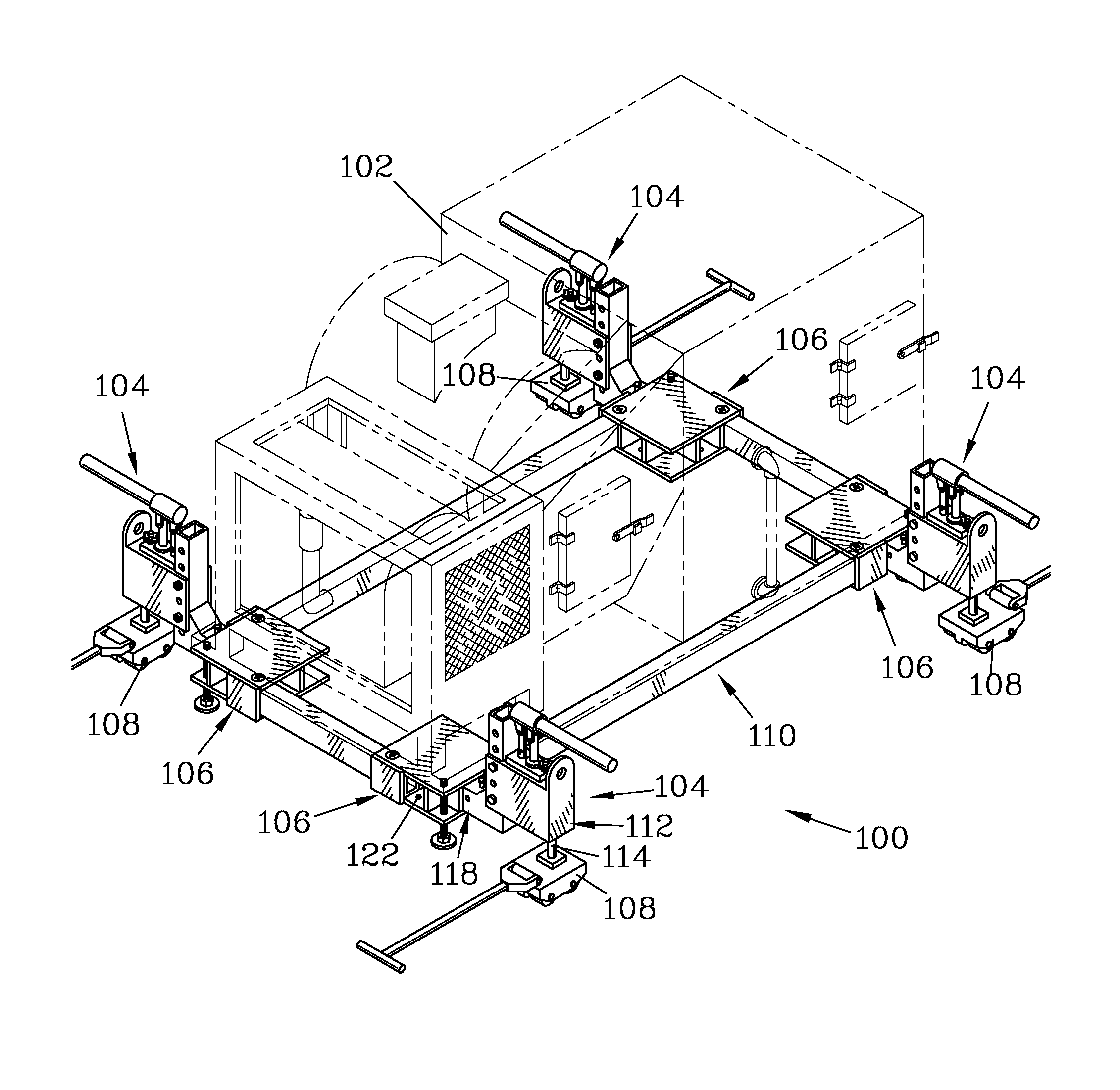
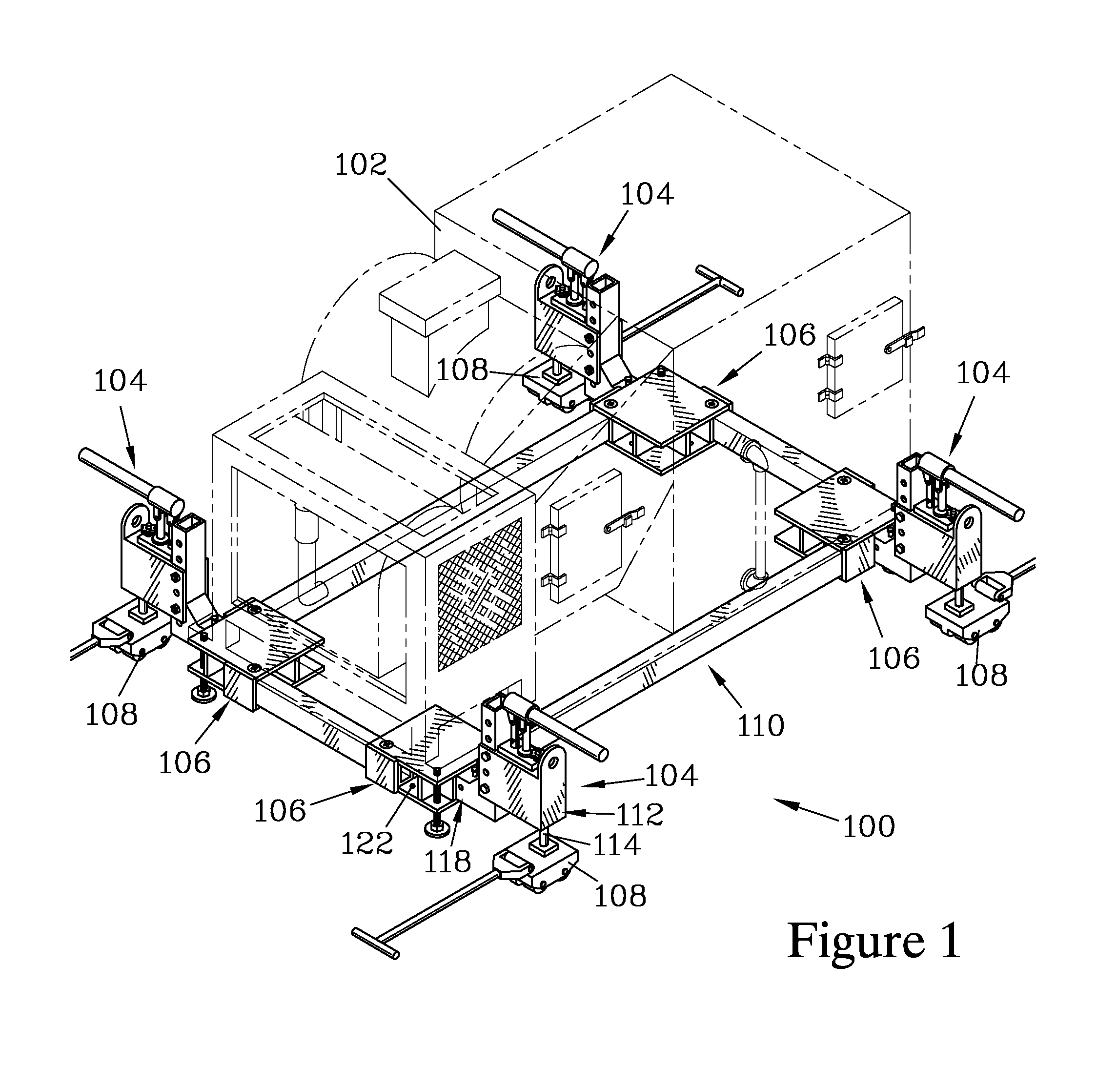
[0039]FIG. 1 is an isometric view of one embodiment of a lifting and transporting system 100 of the present invention, which is shown engaged with a load 102 (shown in phantom in FIG. 1). The system 100 includes a set of jack units 104 that lockably engage coupling elements 106 that, in turn, are secured to the load 102. Each of the jack units 104 has a skate 108 attached thereto, providing a load-bearing support for the jack unit 104 which can be rolled over an underlying surface. In the system 100, four jack units 104 are employed, and the coupling elements 106 form the corners of a frame 110 to which the load 102 is secured by attachment means (not shown), which could include straps, fasteners, welding, or other attachment means known in the art.

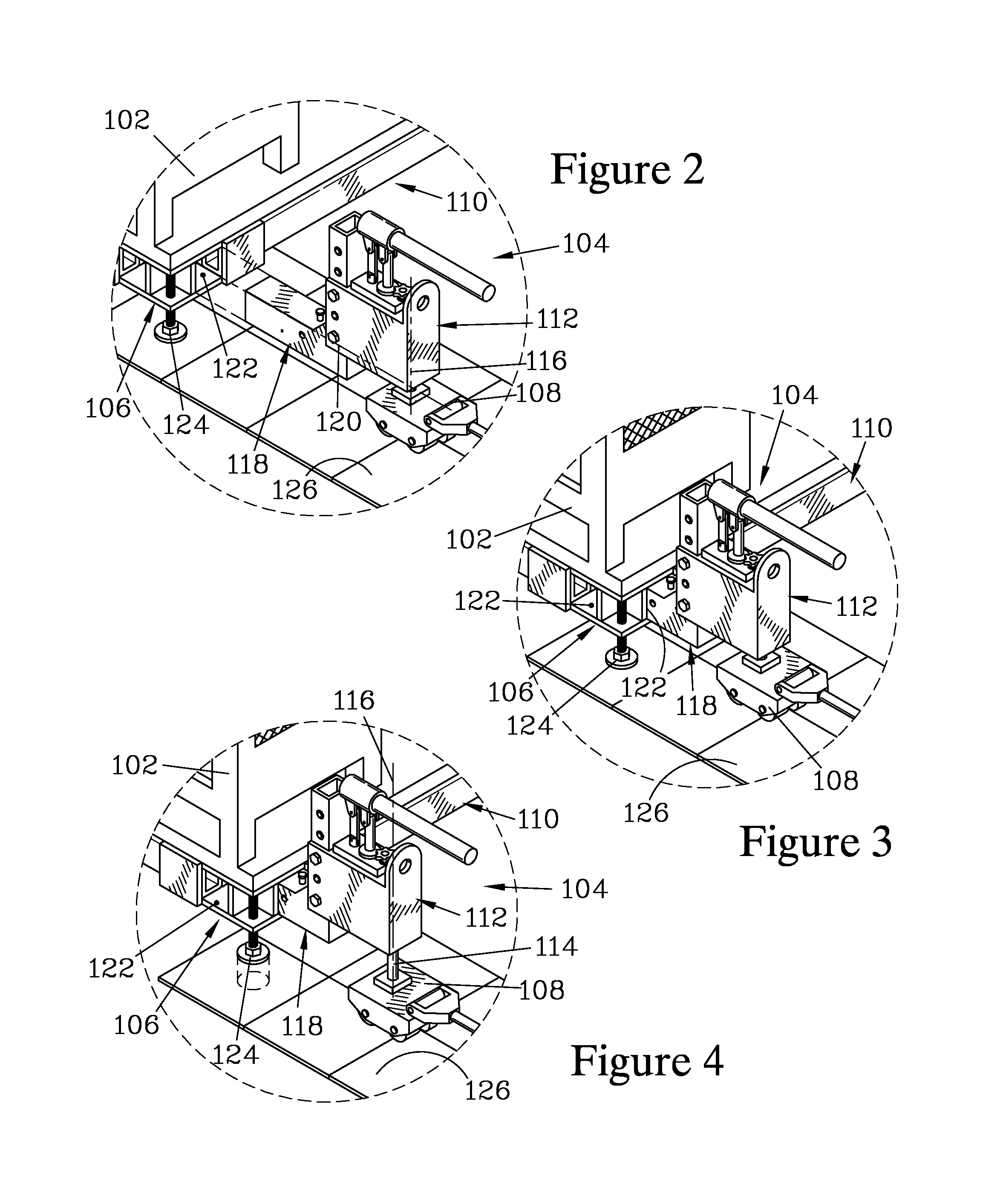
[0040]FIGS. 2-4 illustrate the interaction of one of the jack units 104 with one of the coupling elements 106. The jack unit 104 has a jack housing 112 and an extendable element 114 (shown in FIG. 4) that can be forcibly extended from the...


PUM


Abstract

Jack units are employed to attach skates to an object to be moved. Each jack unit has a tongue that slidably engages a coupling slot affixed to the object, and can be operated to raise or lower the tongue; when raised, the object is supported on the skates and can be rolled to a new location. A crane can attach to lift eyes on the jack units to allow the system to be lifted with the skates attached to the object, avoiding the risk of positioning the skates while the object is suspended. Rotation-limiting structures can be employed to block rotation of the trailing skates to facilitate steering when rolling the object supported by the system. The coupling slots can be provided in coupling elements which can attach directly to the object or which can be employed to form a freestanding frame to which the object is secured.

Description

BACKGROUND OF THE INVENTION[0001]To move objects that are too large and / or heavy to be placed onto a cart, skid, or similar device, it is frequently necessary to lift the object and place skates or rollers (hereinafter simply referred to as “skates”) under the object to support its weight and to allow it to be rolled across a surface to a new location. Such movement causes risks of injury to the movers and damage to the object if the object slips and becomes disengaged from one or more of the skates as it is transported. An additional risk of injury occurs when an object is lowered from a crane onto skates, as moving personnel must work in close proximity to the suspended object in order to position the skates under the object. There is a need to reduce such injury risks to provide greater safety for persons moving large and heavy objects, as well as to reduce the risk of damage due to accidents while such objects are being moved.SUMMARY OF THE INVENTION[0002]The present invention p...

Claims


Application Information

Patent Timeline
IPC IPC(8): B65D19/42B60S11/00
CPCB65D19/42B65D2519/00786B65D2519/00781B60S11/00B66C1/12B66F3/24B66F3/46
Inventor DEBATTISTE, LARRY R.
Owner DEBATTISTE LARRY R
Why Eureka
Try Eureka