Integrated thermal elements in a thermally controlled container

Inactive Publication Date: 2016-08-25
HOGGAN ANDREA
View PDF4 Cites 6 Cited by
  • Summary
  • Abstract
  • Description
  • Claims
  • Application Information

AI Technical Summary

Benefits of technology

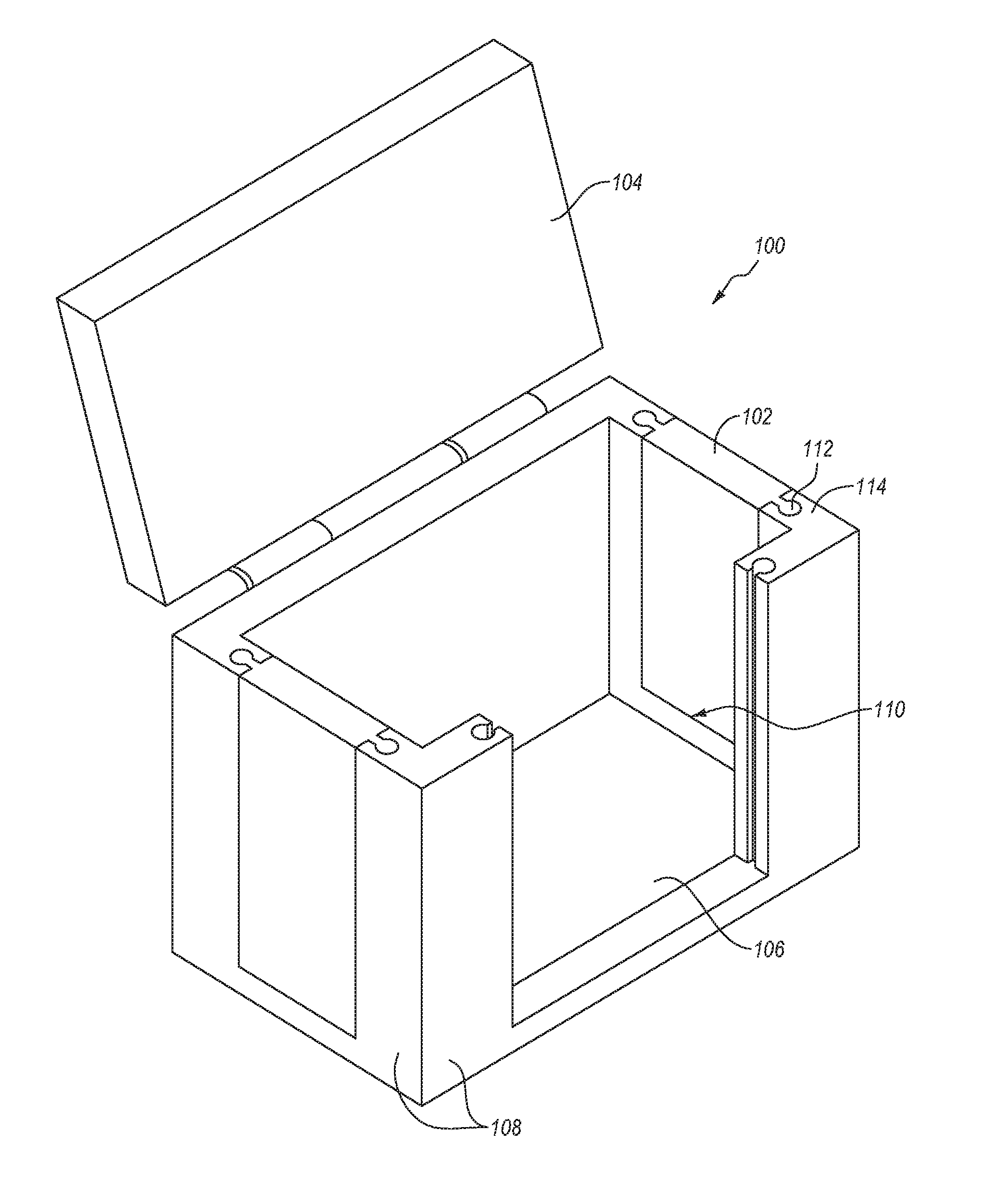
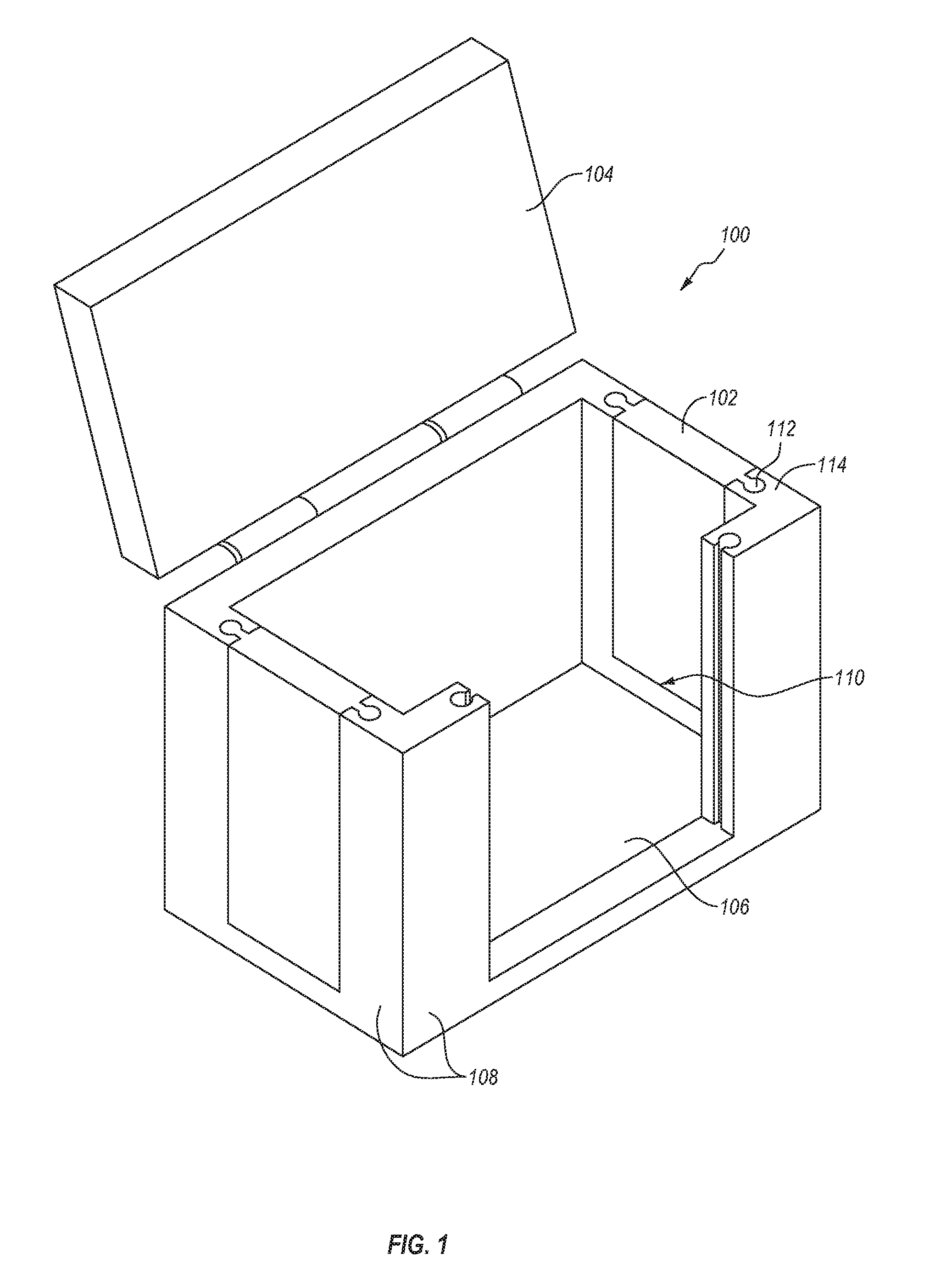
[0008]In another embodiment, a thermally controlled container has a body having a top, a bottom, and one or more walls. At least one of the top, bottom, and one or more walls has an aperture therein that is configured to receive a thermal element. The thermal element is selectively removable and is able to be heated and cooled independently of the body.
[0009]In yet another embodiment, a thermally controlled container has a body with a plurality of walls, a top, and a bottom. The top, bottom, and plurality of walls define an interior volume. At least two of the top, bottom, and one or more walls have an aperture therein that is configured to receive a thermal element. At least one of the apertures is defined by a pluralit

Problems solved by technology

The cooler may limit a rate of increase in temperature of the contents, keeping the contents below the ambient temperature for a longer period of time.
The thermal element may, however, consume valuable space within the container or may produce an environment that is, in at least one aspect, undesirable for the good.
In another aspect, the use of ice may not be acceptably sterile and/or controllable for use in medical applications, such as the transportation of organs or biological matter for transplant or graft.
While dry ice may limit the ex

Method used


Image

  • Integrated thermal elements in a thermally controlled container
  • Integrated thermal elements in a thermally controlled container
  • Integrated thermal elements in a thermally controlled container

Examples


Embodiment Construction

[0021]One or more specific embodiments of the present disclosure will be described below. In an effort to provide a concise description of these embodiments, some features of an actual embodiment may be described in the specification. It should be appreciated that in the development of any such actual embodiment, as in any engineering or design project, numerous embodiment-specific decisions will be made to achieve the developers' specific goals, such as compliance with system-related and business-related constraints, which may vary from one embodiment to another. It should further be appreciated that such a development effort might be complex and time consuming, but would nevertheless be a routine undertaking of design, fabrication, and manufacture for those of ordinary skill having the benefit of this disclosure.

[0022]One or more embodiments of the present disclosure may generally relate to controlling thermal properties of a container. In some embodiments, a thermally controlled ...


PUM


Abstract

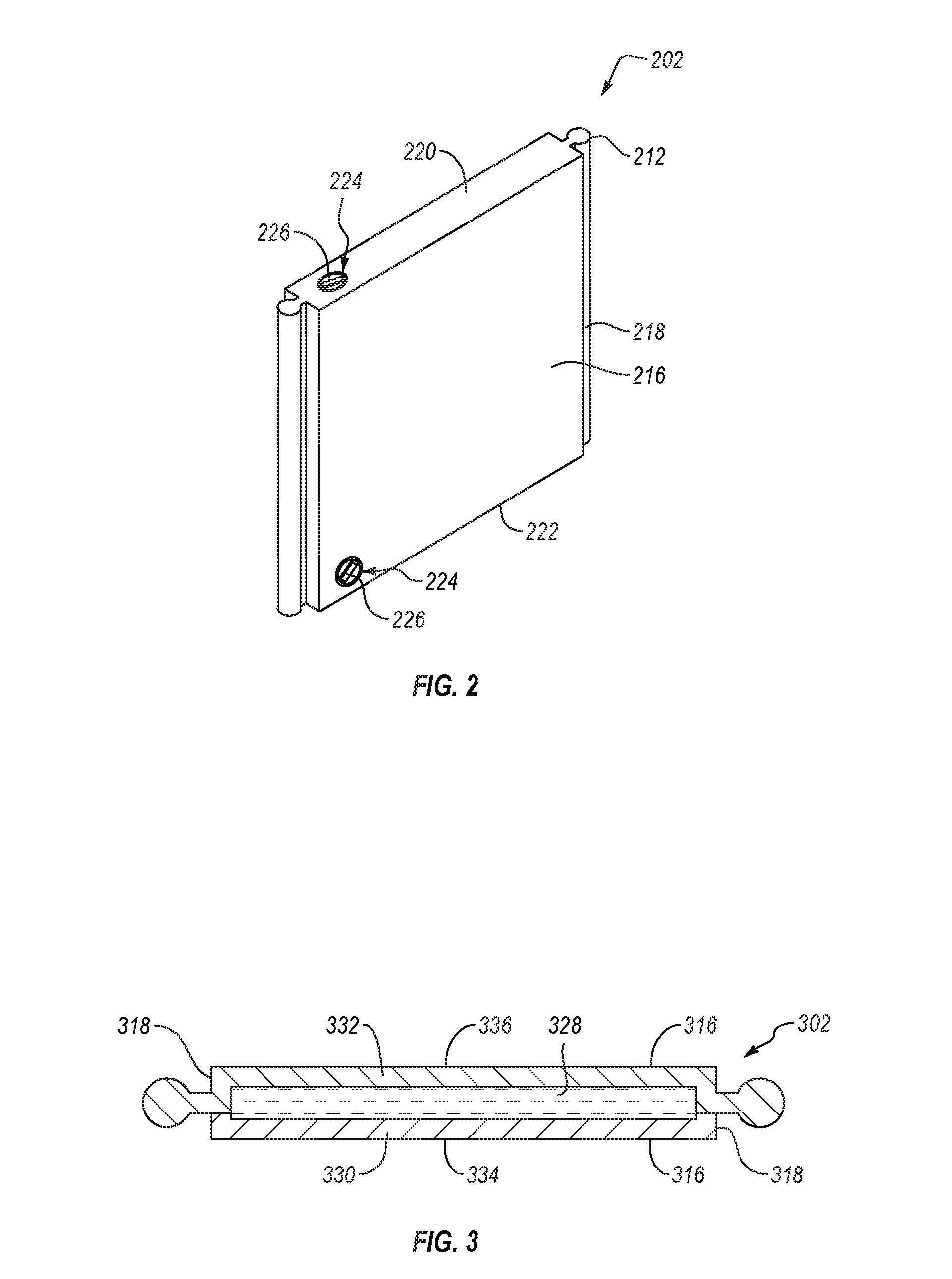
A thermally controlled container includes one or more thermal elements configured to engage with at least one of a top, a bottom, or a plurality of walls of the thermally controlled container. The one or more thermal elements have at least one engagement feature that engages with a body of the thermally controlled container. At least one of the thermal elements forms a part of at least one of the top, a bottom, or a plurality of walls of the thermally controlled container.

Description

CROSS-REFERENCE TO RELATED APPLICATIONS[0001]This application claims priority to U.S. Provisional Patent Application No. 62 / 120,225, filed Feb. 24, 2015, the entire contents of which are incorporated by reference herein.BACKGROUND OF THE DISCLOSURE[0002]Thermally controlled containers may be used to contain objects at or near a desired temperature. An example of a thermally controlled container is a cooler used to insulate the contents of the cooler from a higher ambient temperature. The cooler may limit a rate of increase in temperature of the contents, keeping the contents below the ambient temperature for a longer period of time. The contents may include a food or beverage, such as cheese or juice; a chemical, such as a chemical that is sensitive to temperature changes; organic matter, such as transplant organs; or any other object that may be more desirable and / or useful at a temperature below temperatures comfortable for people. In other examples, a thermally controlled contain...

Claims


Application Information

Patent Timeline
IPC IPC(8): B65D81/38F28D20/02
CPCF28D20/02B65D81/38B65D81/3823F25D3/06F25D2303/083F28D2020/006Y02E60/14
Inventor HOGGAN, ANDREA
Owner HOGGAN ANDREA
Why Eureka
Try Eureka