Detector for detecting electromagnetic waves

a detector and electromagnetic wave technology, applied in the direction of electrical equipment, semiconductor devices, antenna feed intermediates, etc., to achieve the effect of enhancing the sensitivity of the sensor

Inactive Publication Date: 2010-10-19
GLOBALFOUNDRIES INC
View PDF1 Cites 4 Cited by
  • Summary
  • Abstract
  • Description
  • Claims
  • Application Information

AI Technical Summary

Benefits of technology

[0011]The detector according to this aspect of the invention receives the electromagnetic waves by means of the antenna and converts the received electromagnetic radiation into heat by means of the termination section of the semiconductor element. The termination section functions as termination resistor of the antenna. The heat produced in the termination section is used for heating a temperature-sensitive part of the termination section. The temperature-sensitive part can be any part of the semiconductor-element that comprises a measurable temperature-dependent characteristic. Advantageously, the termination section is arranged in the proximity of the temperature-sensitive part. Advantageously, the termination section heats the temperature-sensitive part selectively. In other words, the termination section does not heat the complete semiconductor element evenly or uniformly, but produces the heat at or in the proximity of the temperature sensitive part. In other words, the produced heat is focused on the area of the temperature sensitive part. Such a focusing of the heat on the temperature-sensitive part enhances the sensitivity of the detector.
[0038]According to an embodiment of this aspect of the invention, the thermal imaging device comprises a lens for focusing the electromagnetic waves on the detector. This enhances the sensitivity of the sensor.

Problems solved by technology

The problem of such an approach is to provide suitable solutions that can convert the extremely high-frequency wave as received by the antenna into a signal which can be handled by electronic devices capable of dealing with such high frequencies.

Method used


Image

  • Detector for detecting electromagnetic waves
  • Detector for detecting electromagnetic waves
  • Detector for detecting electromagnetic waves

Examples


Embodiment Construction

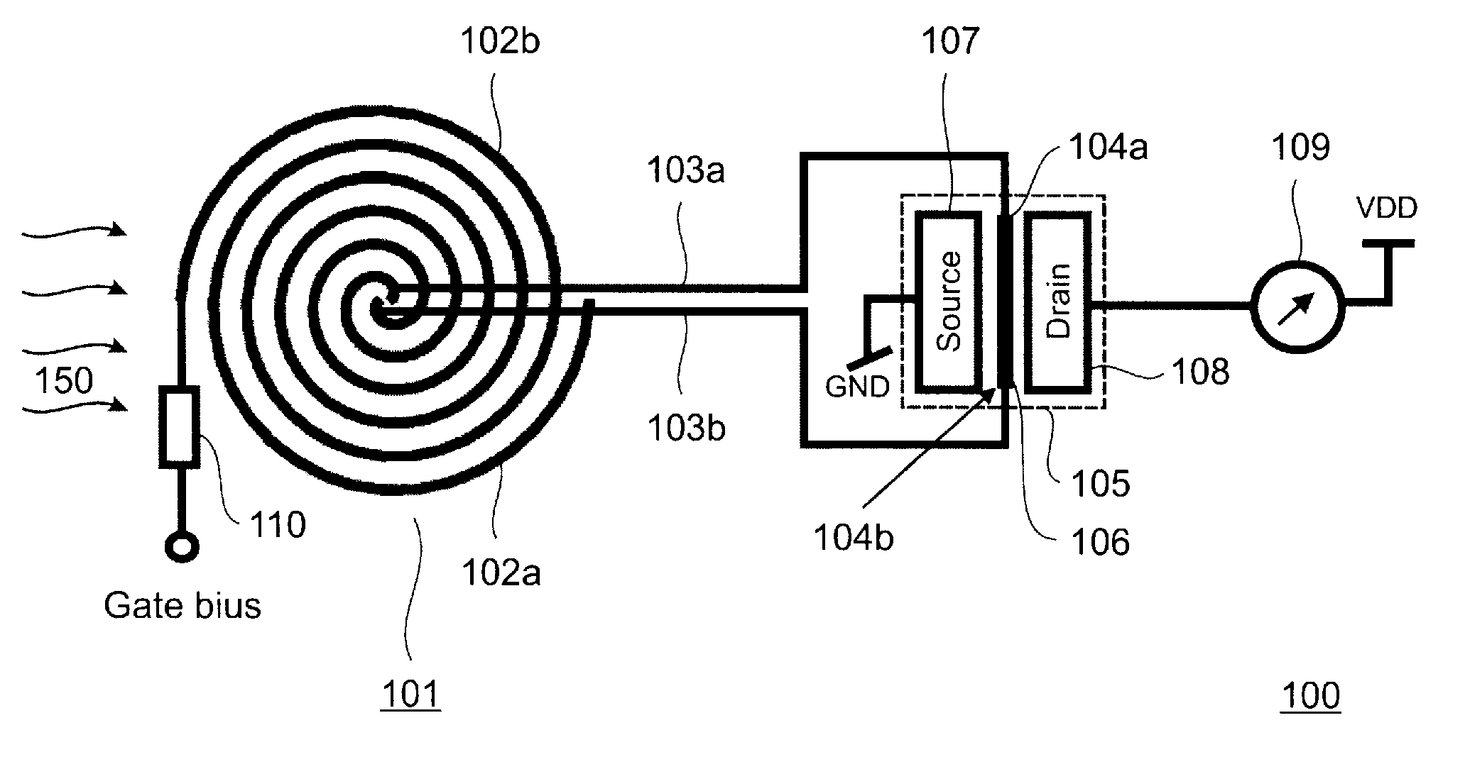
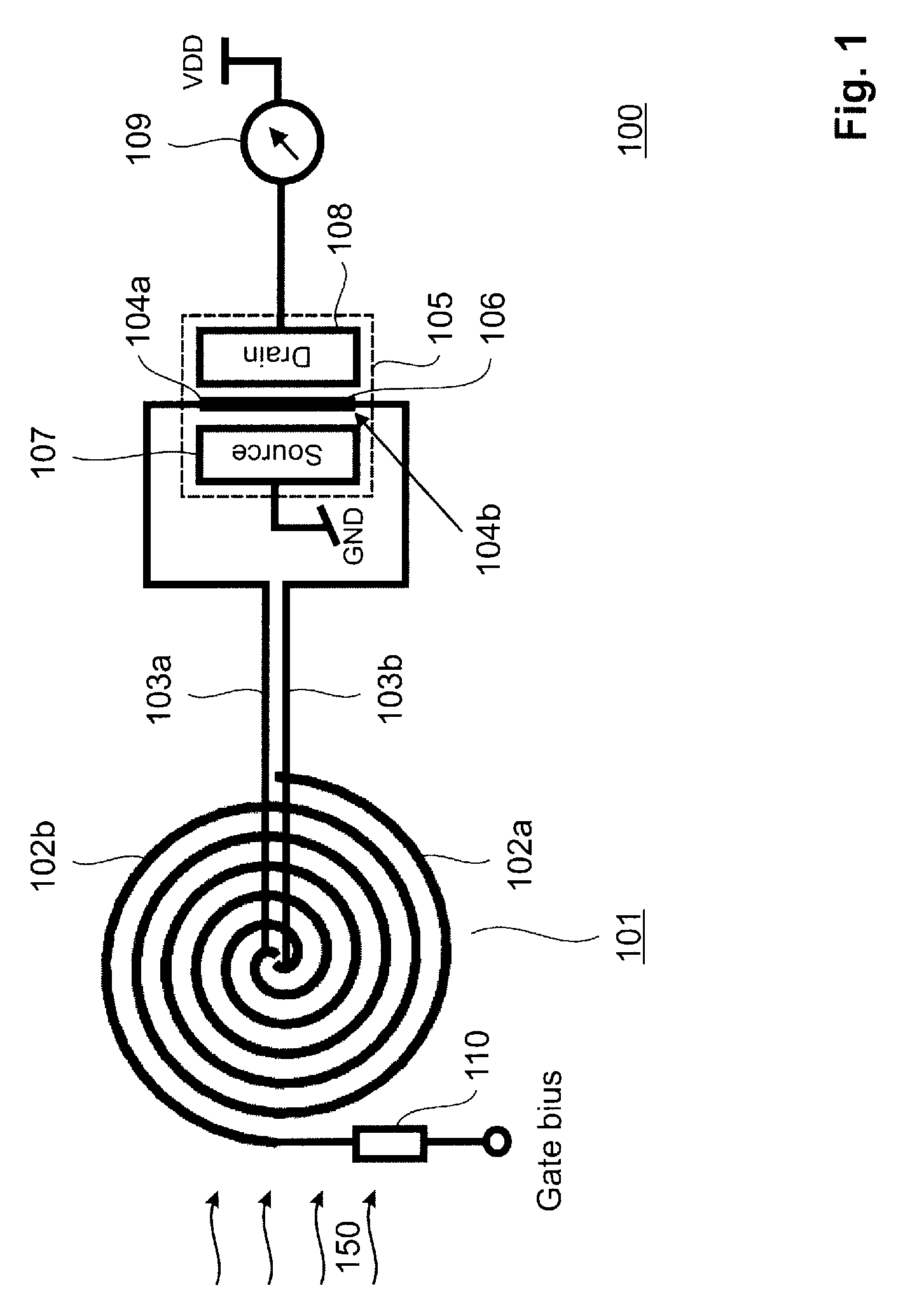
[0049]FIG. 1 shows a schematic illustration of a detector 100 for detecting electromagnetic waves 150 according to an embodiment of the present invention. The detector 100 is in particular suitable for detecting electromagnetic waves 150 with a frequency in the THz range. The detector 100 comprises an antenna 101 for receiving the electromagnetic waves 150. The antenna 101 can be e.g. a planar broadband antenna with a ground plane. The antenna 101 is in particular suited to receive electromagnetic waves in a wavelength range between 3 μm and 15 μm. The antenna 101 comprises a first arm 102a and a second arm 102b. The first arm 102a is connected by means of a first via 103a to a first termination point 104a and the second arm 102b is connected by means of a second via 103b to a second termination point 104b. The first termination point 104a and the second termination point 104b are contact points for contacting a gate 106 of a Field Effect Transistor (FET) 105. Thus the gate 106 of t...


PUM


Abstract

A detector for detecting electromagnetic waves, the detector having an antenna for receiving the electromagnetic waves, a semiconductor element, wherein a termination section of the semiconductor element establishes a termination resistor of the antenna, wherein the termination section is provided for heating a temperature-sensitive part of the semiconductor element, wherein the semiconductor element comprises a temperature-dependent characteristic that is dependent from the temperature of the temperature sensitive part and a measurement unit for measuring the temperature-dependent characteristic of the semiconductor element.

Description

CROSS REFERENCES TO RELATED APPLICATIONS[0001]This application is related to EP Patent Application Number 06116745.8, filed Jul. 6, 2006FIELD OF INVENTION[0002]The present invention is related to a detector for detecting electromagnetic waves and a corresponding thermal imaging device. The present invention is in particular related to detectors for detecting electromagnetic waves in the visible light, infrared and far infrared light range.BACKGROUND OF THE INVENTION[0003]One known way for detecting optical radiation is by means of optical detectors that convert a photon into an electron via electron / hole generation upon impact of a photon in a generation / recombination zone. The sum of the electrons / holes generated by the photons represents a signal current that corresponds to the received optical power. This is equivalent to the number of photons incident to the detector that are actually converted to electrons. The conversion is typically done in a photo diode.[0004]Thanks to the p...

Claims


Application Information

Patent Timeline
Patent Type & Authority Patents(United States)
IPC IPC(8): H01L27/14H01L31/00
CPCH01L31/08H01Q9/27H01L27/1446
Inventor MORF, THOMAS E.SCHMATZ, MARTIN LEOWEISS, JONAS R.
Owner GLOBALFOUNDRIES INC
Why Eureka
Try Eureka