Film deposition apparatus

a technology of film deposition apparatus and film, which is applied in the direction of chemical vapor deposition coating, coating, metal material coating process, etc., can solve the problems of reducing the activation of process gas to be supplied to the substrate, and the response has limitations

Active Publication Date: 2016-08-25
TOKYO ELECTRON LTD
View PDF4 Cites 3 Cited by
  • Summary
  • Abstract
  • Description
  • Claims
  • Application Information

AI Technical Summary

Benefits of technology

[0009]An embodiment of the present invention provides a film deposition apparatus that can adjust uniformity of film deposition across a surface of a substrate while implementing activation of a gas.

Problems solved by technology

However, when there is a demand of film deposition under further higher pressure conditions in the future, the flow rate of carrier N2 gas is increased for the gas displacement to respond to the demand, but such a response has limitations because the increase of the supply of N2 gas causes the decrease of the activation of the process gas to be supplied to the substrates.

Method used


Image

  • Film deposition apparatus
  • Film deposition apparatus
  • Film deposition apparatus

Examples


Embodiment Construction

[0022]A description is given below of embodiments of the present invention with reference to accompanying drawings.

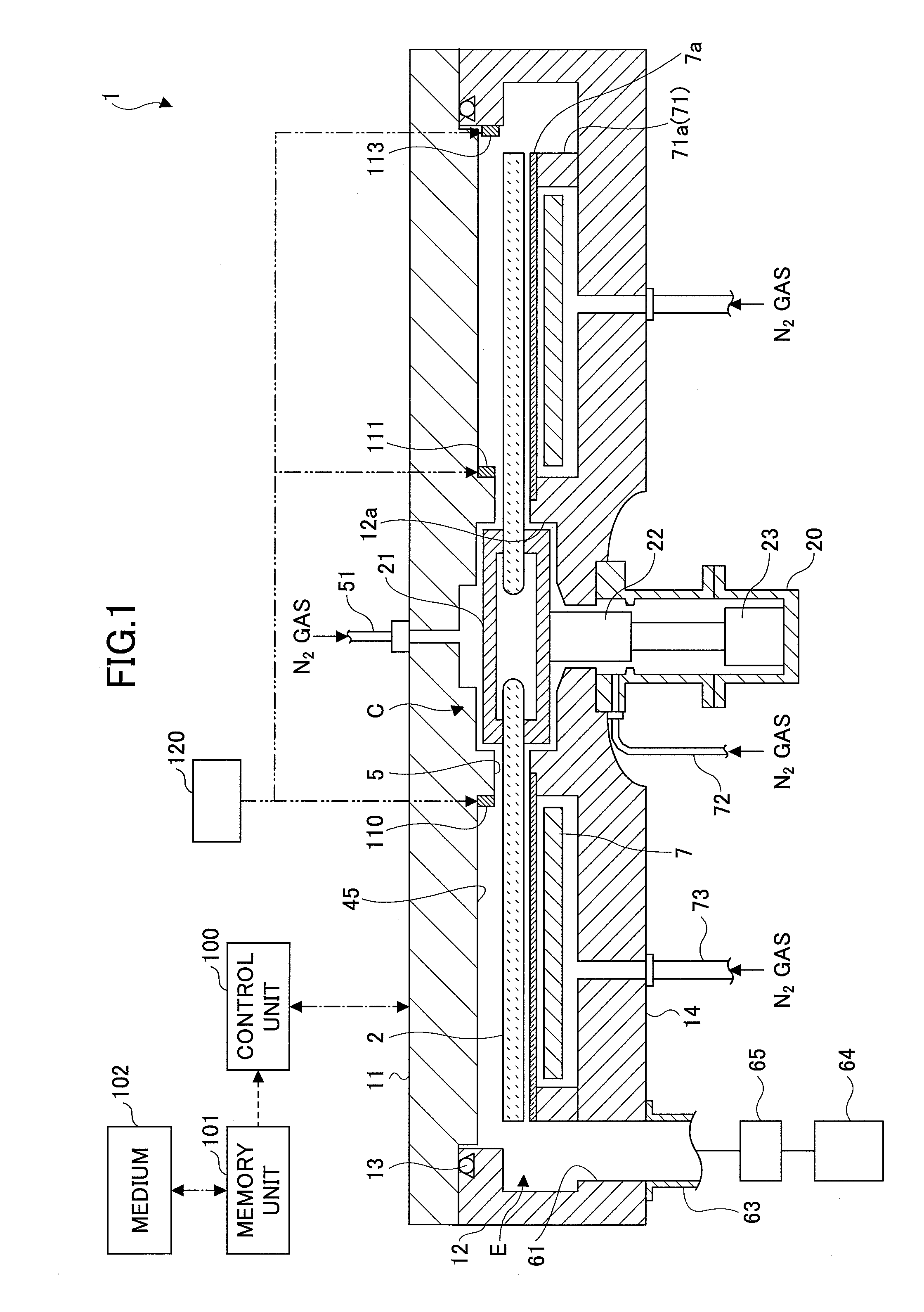
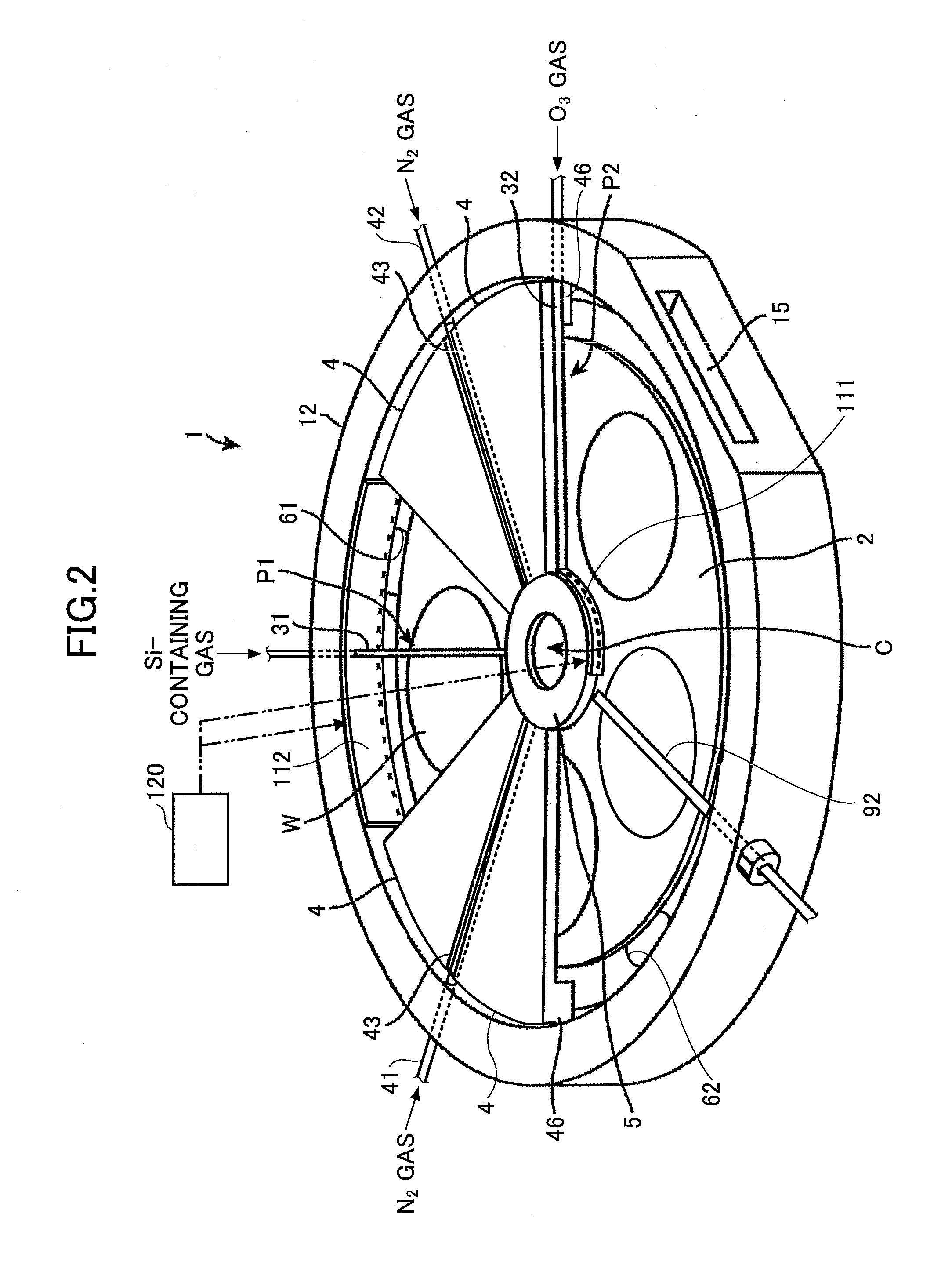
[0023]FIG. 1 is a vertical cross-sectional view of an example of a film deposition apparatus according to an embodiment of the present invention. FIG. 2 is an exploded perspective view of an example of the film deposition apparatus according to an embodiment of the present invention. FIG. 3 is a exploded top view of an example of the film deposition apparatus according to an embodiment of the present invention.

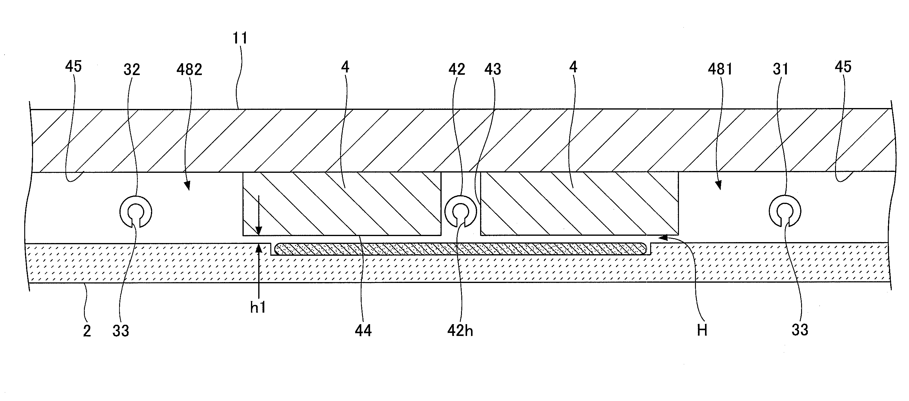
[0024]With reference to FIGS. 1 through 3, the film deposition apparatus according to an embodiment of the present invention is provided with a vacuum chamber 1 having a flattened cylindrical shape, and a turntable 2 that is located inside the chamber 1 and has a rotational center at a center of the vacuum chamber 1. The vacuum chamber 1 is composed of a chamber body 12 having a cylindrical shape with a closed bottom and a ceiling plate 11 that is detachably place...


PUM

PropertyMeasurementUnit
diameteraaaaaaaaaa
temperatureaaaaaaaaaa
frequencyaaaaaaaaaa

Abstract

A film deposition apparatus includes a process chamber having a substantially cylindrical shape, and a turntable to receive a substrate thereon provided in the process chamber. At least one gas nozzle extends toward a central axis of the turntable from an inner side wall of the process chamber above the turntable along a radial direction of the turntable. At least one side wall heater is provided to cover at least part of the inner side wall of the process chamber and/or at least part of a surrounding area of the central axis of the turntable in a wall-shaped manner.

Description

CROSS-REFERENCE TO RELATED APPLICATION[0001]The present application is based upon and claims the benefit of priority of Japanese patent application No. 2015-032804, filed on Feb. 23, 2015, the entire contents of which are incorporated by reference in their entirety.BACKGROUND OF THE PRESENT INVENTION[0002]1. Field of the Present Invention[0003]The present invention relates to a film deposition apparatus.[0004]2. Description of the Related Art[0005]Conventionally, as disclosed in Japanese Laid-Open Patent Application Publication No. 2013-118411, a turntable-type film deposition apparatus using ALD (Atomic Layer Deposition) or MLD (Molecular Layer Deposition) is known. The film deposition apparatus includes a turntable capable of receiving a plurality of substrates along a circumferential direction of the turntable in a vacuum chamber, and a first reaction gas supply part and a second reaction gas supply part provided apart from each other in a rotational direction of the turntable. I...

Claims


Application Information

Patent Timeline
Patent Type & Authority Applications(United States)
IPC IPC(8): C23C16/455C23C16/458C23C16/46
CPCC23C16/45544C23C16/45563C23C16/458C23C16/46C23C16/45578
Inventor KATO, HITOSHIMIURA, SHIGEHIRO
Owner TOKYO ELECTRON LTD
Why Eureka
Try Eureka