Purging method and structure, deposition process and gas inlet system

A technology of process gas and purge gas, which is applied in the direction of electrical components, semiconductor/solid-state device manufacturing, circuits, etc., to achieve the effect of promoting continuous progress

Pending Publication Date: 2020-10-30
BEIJING NAURA MICROELECTRONICS EQUIP CO LTD
View PDF7 Cites 2 Cited by
  • Summary
  • Abstract
  • Description
  • Claims
  • Application Information

AI Technical Summary

Problems solved by technology

[0008] The present invention aims to solve at least one of the technical problems existing in the prior art, and proposes a purging method and structure, a deposition process and an air intake system to solve the problem of gas uniformity at the edge of the substrate in the prior art

Method used


Image

  • Purging method and structure, deposition process and gas inlet system
  • Purging method and structure, deposition process and gas inlet system

Examples


Embodiment Construction

[0037] In order for those skilled in the art to better understand the technical solution of the present invention, the purging method and structure, deposition process and air intake system provided by the present invention will be described in detail below with reference to the accompanying drawings.

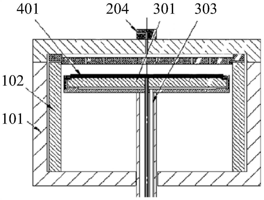
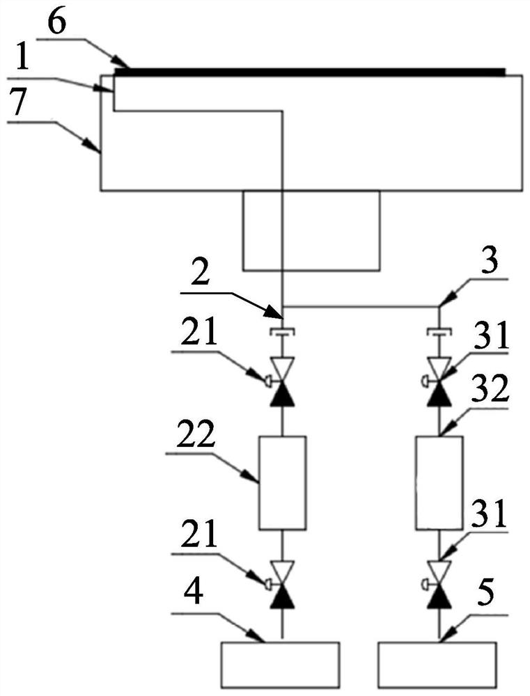
[0038] As an aspect of the present invention, an embodiment of the present invention provides a purging method used in a chemical vapor deposition process, wherein the substrate is carried on a chuck, and the purging method includes:

[0039] During the chemical vapor deposition process, purge and process gases are delivered to the edge of the substrate.

[0040] Since the purge gas and process gas are fed to the edge of the substrate, the process gas reacts with the process gas fed into the chamber to promote the continuation of the reaction at the edge of the substrate to supplement the products on the edge of the substrate and adjust The uniformity of the edge of the substra...


PUM


Abstract

The invention provides a purging method and structure, a deposition process and a gas inlet system. The purging method is used in the chemical vapor deposition process. A substrate is borne on a chuck, and purging gas and process gas are conveyed to the edge of the substrate in the process of carrying out the chemical vapor deposition process. Due to the fact that the purging gas and the process gas are introduced into the edge of the substrate, the process gas reacts with process gas introduced into a cavity, continuous proceeding of the reaction on the edge of the substrate is promoted, products on the edge of the substrate are supplemented, and thus the uniformity of the edge of the substrate is adjusted.

Description

technical field [0001] The invention belongs to the technical field of semiconductor manufacturing, and in particular relates to a purging method and structure, a deposition process and an air intake system. Background technique [0002] In the integrated circuit (IC) manufacturing process, especially in the chemical vapor deposition (CVD) process, in order to fix, support and transfer the wafer and realize temperature control, and avoid movement or dislocation during the process, vacuum cards are usually used Disk (Vacuum Chuck). [0003] figure 1 It is a structural schematic diagram of a vacuum chuck in the prior art. Such as figure 1 As shown, the vacuum chuck 301 is used to carry the substrate 401 , and the chamber 101 together with the lining 102 and the vacuum chuck 301 constitute a process environment. Before performing the process, the gas inlet 204 will be fed with Ar or N 2 , keep the process pressure in the chamber, and at the same time open the back-blowing ...

Claims


Application Information

Patent Timeline
Patent Type & Authority Applications(China)
IPC IPC(8): H01L21/02H01L21/67
CPCH01L21/02H01L21/67017
Inventor 张军郑波马振国张少雷
Owner BEIJING NAURA MICROELECTRONICS EQUIP CO LTD
Why Eureka
Try Eureka