Driving method for vibration body, vibration driving device, and image pickup apparatus

a technology of driving device and vibration body, which is applied in the direction of piezoelectric/electrostrictive device details, instruments, television systems, etc., can solve the problems of deteriorating dust efficiency, affecting the appearance of the image, and affecting the efficiency of moving dust, etc., and achieves the effect of easy miniaturization

Active Publication Date: 2016-08-25
CANON KK
View PDF2 Cites 4 Cited by
  • Summary
  • Abstract
  • Description
  • Claims
  • Application Information

AI Technical Summary

Benefits of technology

[0013]The present invention provides a driving method for a vibration body that is capable of exciting a vibration of desired amplitude wi...

Problems solved by technology

Accordingly, when dust etc. adheres to front faces of these filters, dust-adhered parts are projected as black points in a photographed image, which deteriorates appearance of the image.
In these spots, the dust cannot be moved in the desired direction, or efficiency to move dust det...

Method used


Image

  • Driving method for vibration body, vibration driving device, and image pickup apparatus
  • Driving method for vibration body, vibration driving device, and image pickup apparatus
  • Driving method for vibration body, vibration driving device, and image pickup apparatus

Examples


third embodiment

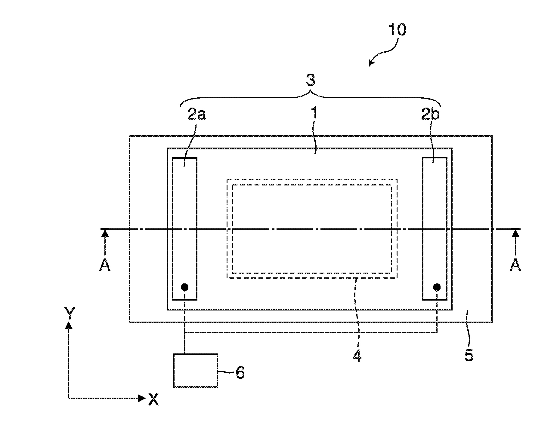
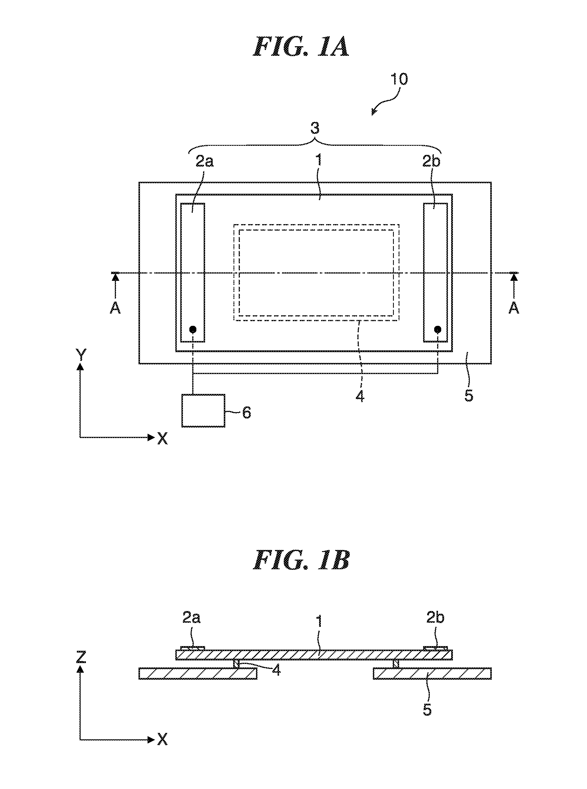
[0060]FIG. 7A is a perspective view schematically showing a configuration of the vibration driving device 20 according to the present invention. The vibration driving device 20 is provided with the vibration body 21 and a slider 22 as the driven body. The vibration body 21 is provided with an elastic body 26, a piezoelectric device 27 joined to a first side of the elastic body 26, and a support member 28 for fixing the elastic body 26 to a base (not shown). The slider 22 is held by a pressurizing member (not shown) in a state where the slider 22 contacts with a second side (the side opposite to the first side on which the piezoelectric device 27 is joined) of the vibration body 21 while giving pressure thereto.

[0061]The slider 22 has a slider base 23 of an angle rod form made from magnet material, a spring member 24, and a friction member 25. The friction member 25 frictionally slides relative to the vibration body 21. Accordingly, the friction member 25 is made from material having...

first embodiment

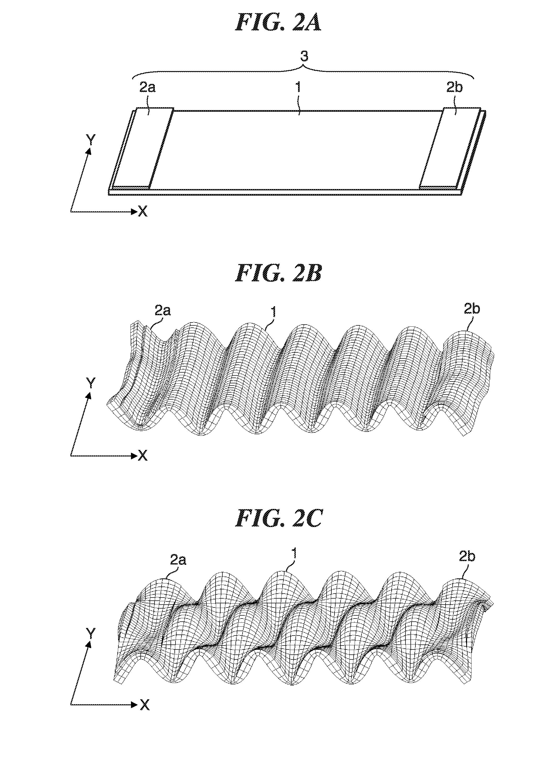
[0068]The vibration in the total order of “[12, 0]” is used in the vibration mode A, and the vibration in the total order of “[11, 1]” is used in the vibration mode B. When the alternation voltages between which the phase difference is 90 degrees are applied to the first electrodes 27a and the second electrodes 27b through the flexible printed circuit board (not shown), the composite vibration (traveling wave) described with reference to FIG. 4A through FIG. 4F and FIG. 5A through FIG. 5F is excited as with the

[0069]When focusing on one point of the wave of the composite vibration, an elliptic motion as indicated by the arrow “b” shown in FIG. 4A occurs in the Z-X plane in the elastic body 26. Accordingly, the slider 22 that contacts with the elastic body 26 while giving pressure receives friction drive force (thrust) from the elastic body 26, and moves in the direction of the elliptic motion (the direction opposite to the traveling direction of the traveling wave).

[0070]Since the m...


PUM


Abstract

A vibration driving device that is capable of exciting a vibration of desired amplitude with a low voltage. A vibration body has a plate-like elastic body and an electro-mechanical energy conversion element that is joined to the elastic body. A control unit excites a vibration in a first vibration mode and a vibration in a second vibration mode in the vibration body by applying alternation voltages to the electro-mechanical energy conversion element. Orders or numbers of nodes of the vibrations in the first and second modes in a first direction that intersects perpendicularly with a thickness direction of the elastic body are mutually different by one. And orders or numbers of nodes of the vibrations in the first and second modes in a second direction that intersects perpendicularly with the thickness direction of the elastic body and the first direction are mutually different by one.

Description

BACKGROUND OF THE INVENTION[0001]1. Field of the Invention[0002]The present invention relates to a technique that excites a vibration on an elastic body so as to remove dust etc. adhered to the elastic body or so as to relatively move the elastic body and a driven body by contacting the elastic body to the driven body, for example.[0003]2. Description of the Related Art[0004]An image pickup apparatus, such as a digital camera, receives an imaging light flux with an image pickup device, such as a CCD sensor and a CMOS sensor, converts an electrical signal output from the image pickup device into image data, and stores the image data into a storage media, such as a memory card. Such an image pickup apparatus generally has an optical low pass filter and an infrared absorption filter arranged at an object side of the image pickup device. Accordingly, when dust etc. adheres to front faces of these filters, dust-adhered parts are projected as black points in a photographed image, which de...

Claims


Application Information

Patent Timeline
IPC IPC(8): G02B27/00H02N2/14H01L41/04G02B7/04H04N5/225
CPCG02B27/0006G02B7/04H02N2/14H01L41/042H04N5/225H02N2/06H02N2/08G02B7/08H04N23/811H10N30/802
Inventor SHIMADA, AKIRA
Owner CANON KK
Why Eureka
Try Eureka