Distortion compensation circuit

Active Publication Date: 2016-08-25
LINEAR TECH LLC
View PDF5 Cites 0 Cited by
  • Summary
  • Abstract
  • Description
  • Claims
  • Application Information

AI Technical Summary

Benefits of technology

The patent text describes a method for compensating for distortion in communication systems by using a circuit to cancel out unwanted signals. The patent describes various methods for canceling out distortion products that can occur in the system, including intermodulation distortion and harmonic distortion. The technical effect of the patent is to provide a more effective and precise method for canceling out distortion in communication systems, allowing for better performance and improved performance of the system.

Problems solved by technology

Communication systems include various circuits, such as receiver demodulators and baseband amplifiers, which have nonlinearities that may lead to “unwanted signals.” The nonlinear behavior of such circuits induces intermodulation products that, together with the system noise, increase the amount of signal distortion, thereby lowering the system performance.
The '649 patent is not readily applicable to baseband signal paths and cannot be readily used to correct for both mixer baseband distortion and baseband amplifier distortion.
If the mixer already has low common-mode IM2 distortion products, there may not be enough IM2 input signal to generate the required output differential IM2 compensation signal.
Since the '867 patent uses a digital approach, it does not have the potential precision that is offered by calculating IM2 distortion in the analog domain.
The methods of the '824, '649, and '646 patents may not allow for independent control of all of the distortion components, namely IM2, HD2, IM3, HD3.
There are many older approaches that involve feed-forward or pre-distortion and make use of delay lines and couplers, which cannot be easily integrated on chip.

Method used


Image

  • Distortion compensation circuit
  • Distortion compensation circuit
  • Distortion compensation circuit

Examples


Embodiment Construction

[0030]In the following detailed description, numerous specific details are set forth by way of examples in order to provide a thorough understanding of the relevant teachings. However, it should be apparent that the present teachings may be practiced without such details. In other instances, well-known methods, procedures, components, and / or circuitry have been described at a relatively high-level, without detail, in order to avoid unnecessarily obscuring aspects of the present teachings. Some embodiments may be practiced with additional components or steps and / or without all of the components or steps that are described.

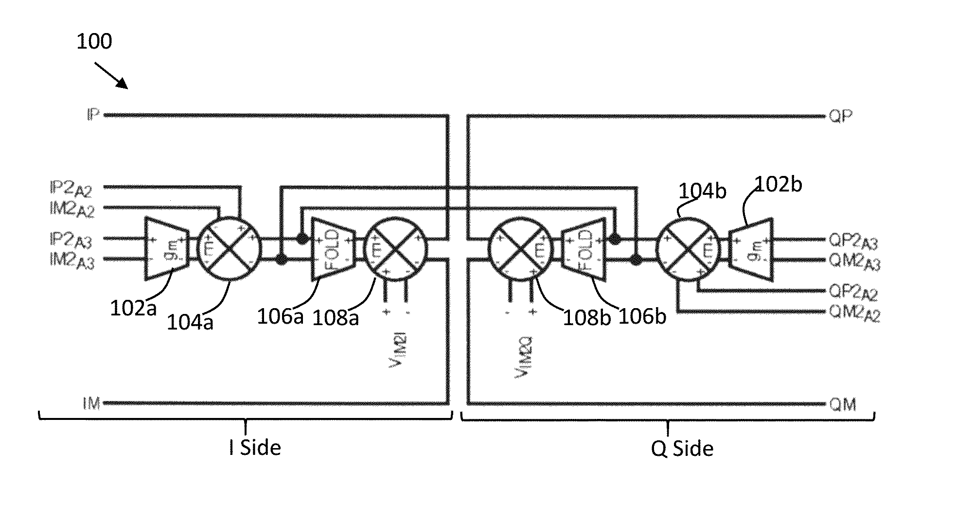
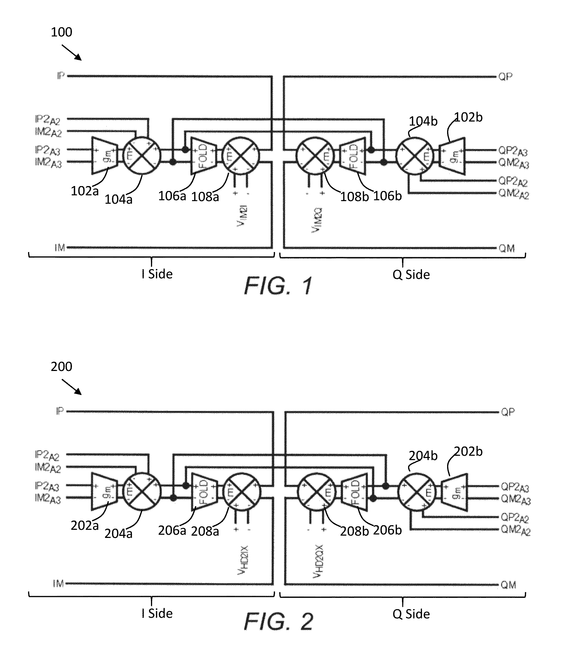
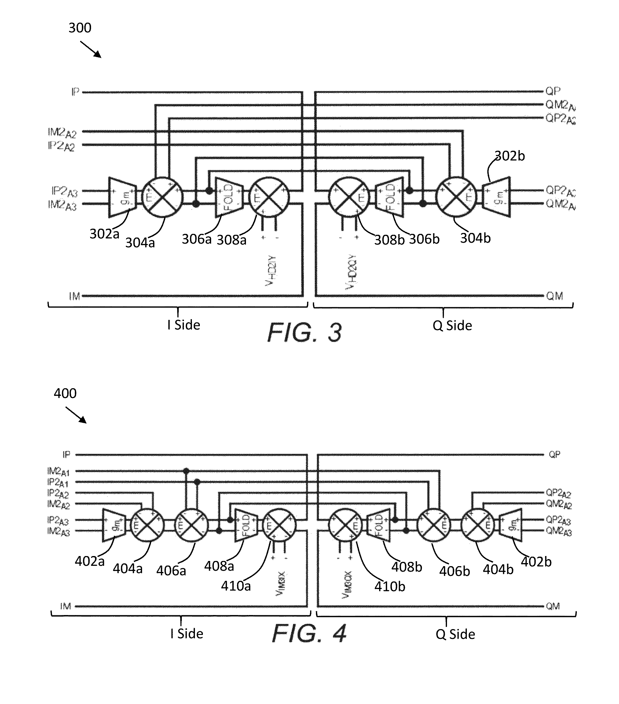
[0031]The various methods and circuits disclosed herein generally relate to circuits and methods for correcting distortion for in-phase and quadrature component signals. In one aspect, a distortion compensation circuit compensates for distortion in a baseband quadrature Q signal and a corresponding baseband in-phase I signal. The distortion compensation circuit incl...


PUM


Abstract

A method and system of compensating for distortion in a baseband in-phase (I) and a corresponding baseband quadrature (Q) signal. The circuit includes an in-phase I attenuator configured to attenuate the baseband in-phase I signal and an in-phase Q attenuator configured to attenuate the baseband Q signal. There are one or more circuits that are configured to receive the attenuated in-phase I signal and the attenuated baseband Q signal. Each circuit performs a different calculation based on predetermined equations configured to determine the IM2, HD2@0°, HD2@90°, IM3@0°, IM3@90°, HD3@0°, and HD3@90°. The distortion compensation circuit is configured to use the result of at least one of the calculation circuits to generate I and Q distortion compensation signals.

Description

CROSS REFERENCES TO RELATED APPLICATIONS[0001]The present application claims the benefit of priority under 35 U.S.C. §119 from U.S. Provisional Patent Application Ser. No. 62 / 120,711, entitled “Distortion Compensation Circuit,” filed on Feb. 25, 2015, and from U.S. Provisional Patent Application Ser. No. 62 / 134,389, entitled “Distortion Compensation Circuit,” filed on Mar. 17, 2015, which are hereby incorporated by reference in its entirety for all purposes.BACKGROUND[0002]1. Technical Field[0003]This disclosure generally relates to distortion compensation, and more particularly to circuits and methods for correcting distortion for in phase and quadrature component signals.[0004]2. Description of Related Art[0005]Communication systems include various circuits, such as receiver demodulators and baseband amplifiers, which have nonlinearities that may lead to “unwanted signals.” The nonlinear behavior of such circuits induces intermodulation products that, together with the system nois...

Claims


Application Information

Patent Timeline
IPC IPC(8): H04L27/36H04B1/04
CPCH04L27/364H04B1/0475H03D2200/0088H03F1/3241H03C2200/0083H03D3/009H03F1/3211H03F1/3247H03F3/4508H03F3/45475H04B1/1036H04B3/32H04L25/03343H04L27/368
Inventor MYERS, JOHN PERRY
Owner LINEAR TECH LLC
Why Eureka
Try Eureka