Skin treatment device providing optical coupling to skin tissue

a skin treatment device and optical coupling technology, applied in the field of skin treatment devices providing optical coupling to skin tissue, can solve the problems of increased damage to skin tissue surrounding the treatment position, unsatisfactory quality of focusing treatment light from the light source to the focus position, and more expensive skin treatment devices. achieve the effect of effective light delivery

Active Publication Date: 2016-09-01
KONINKLJIJKE PHILIPS NV
View PDF3 Cites 1 Cited by
  • Summary
  • Abstract
  • Description
  • Claims
  • Application Information

AI Technical Summary

Benefits of technology

The invention is based on the discovery that when an indenter is pressed against the skin surface, a skin protrusion occurs, which causes a curved surface that matches the shape of the indenter. The inventors found that the height of the protrusion is important in determining the quality of the focused treatment light. By controlling the position of the protrusion, the radius of curvature of the wave front can be matched, reducing spherical aberration and improving the focus of the treatment light. The invention also includes a method for measuring the height of the protrusion and a look-up table to determine the optimal width dimension of the aperture. The invention aims to improve the quality and effectiveness of light-based skin treatment devices by reducing spherical aberration and improving the focus of the treatment light.

Problems solved by technology

This typically increases the requirements to be met by the light sources used in such skin treatment devices, causing said skin treatment devices to be more expensive, and the increased overall intensity of the treatment light increases possible damage to skin tissue surrounding the treatment position, which is also undesirable.
Consequently, in the known skin treatment devices the quality of focusing the treatment light from the light source to the focus position is not optimal, which requires the known skin treatment devices to use an excess of light energy to produce this light-based treatment process.

Method used


Image

  • Skin treatment device providing optical coupling to skin tissue
  • Skin treatment device providing optical coupling to skin tissue
  • Skin treatment device providing optical coupling to skin tissue

Examples


first embodiment

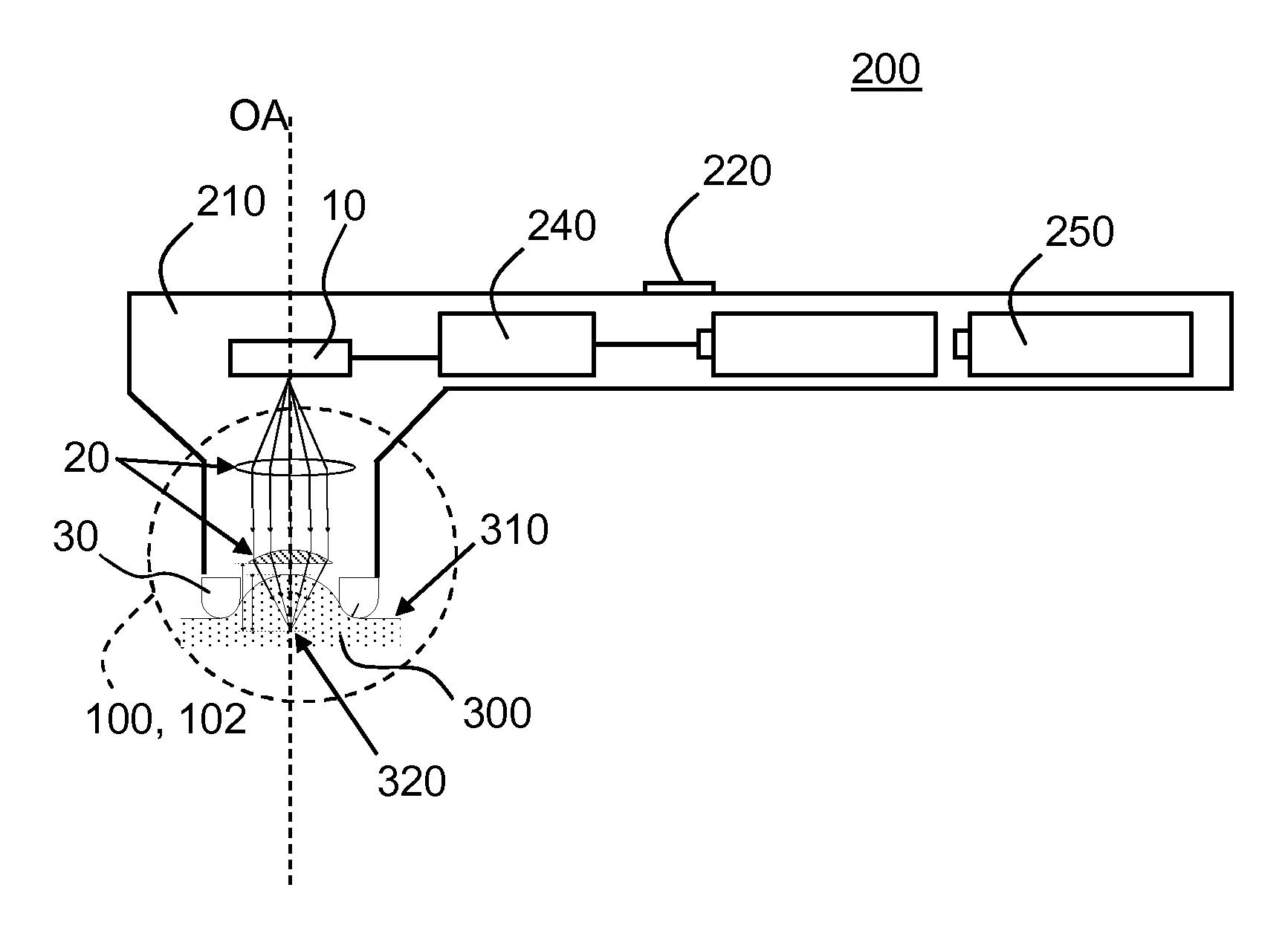
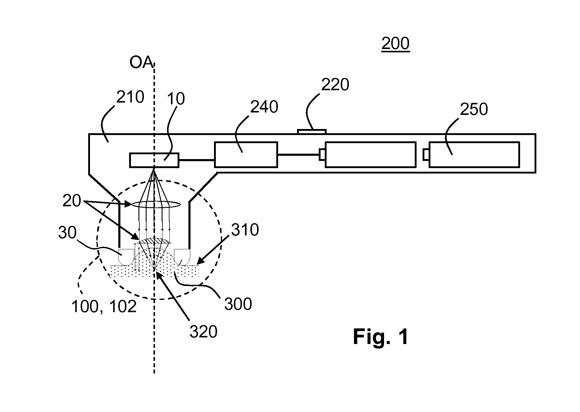
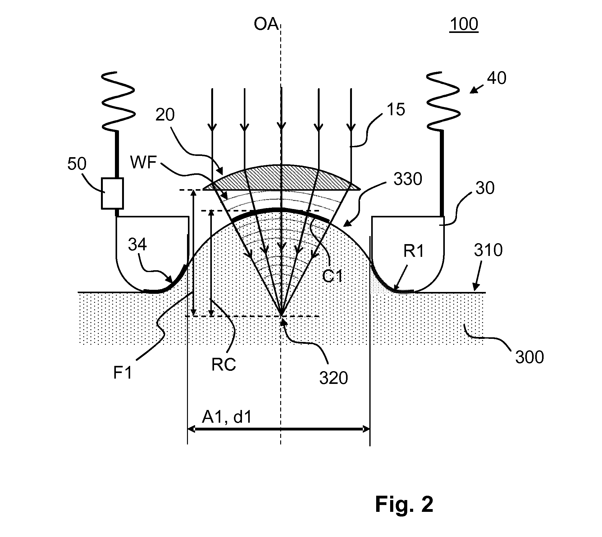
[0030]FIG. 2 diagrammatically shows an indenter construction 100 for the skin treatment device 200 according to the invention. FIG. 2 shows part of the optical system 20 focusing the treatment light 15 into the skin tissue 300. Also shown are the wave fronts WF of the focused treatment light 15 as the focused treatment light 15 progresses towards the skin surface 310 of the curved protrusion 330 freely protruding inside the aperture A1. When the pressure at which the indenter 30 is pressed against the skin surface 310 exceeds the predefined pressure, the radius of curvature RC of the curved skin surface of the curved protrusion 330 freely protruding inside the aperture A1 having a specific width dimension d1 for a specific skin type is well defined, said curved protrusion constituting a maximally curved protrusion 330. The optical system 20 is configured and arranged to focus the treatment light 15 such as to generate a wave front WF at the skin surface 310 of the maximally curved p...

second embodiment

[0035]FIG. 3 diagrammatically shows the indenter construction 102 for the skin treatment device 200 according to the invention. In this embodiment, the optical system 22 is constructed to generate a plurality of spatially separate focusing positions 322 inside the skin tissue 300. In the embodiment shown in FIG. 3, the optical system 22 comprises a first optical element 22A for focusing the treatment light 15 from, for example, a laser light source 10 (not shown) to a moving mirror 22B which sequentially redirects the treatment light 15, via a projection lens 22C, to individual different focusing lenses 22D in an array of focusing lenses 22D. Each of the different focusing lenses 22D focuses the treatment light 15 along the individual optical axis OAn into the skin tissue 300 to the individual focusing positions 322. A benefit of this sequential focusing of the treatment light 15 into the different focusing positions 322 is that the intensity of the treatment light 15 required for t...


PUM


Abstract

The invention provides a non-invasive skin treatment device (200) comprising: a light source (10) constructed for emitting treatment light (15), an optical system (20) constructed for focusing the treatment light along an optical axis (OA) to a focus position (320) inside the skin tissue (300), and an indenter (30) comprising a skin contact surface (34) having an aperture (A1) at a distance from the optical system for allowing the treatment light to be focused through the aperture into the skin tissue. The indenter is configured and constructed for generating, in a cross-section of the aperture taken along the optical axis and along a cross-section direction wherein the aperture has a width dimension, a maximally curved protrusion of skin tissue freely protruding through the aperture towards the optical system by pressing the indenter against the skin surface of a specific skin type with a pressure exceeding a predefined pressure, a skin surface of said maximally curved protrusion having a radius of curvature (RC) at an intersection with the optical axis. The optical system is configured and constructed for generating a focused beam of the treatment light having, in said cross-section of the aperture at said intersection, a wave front with a radius of curvature ranging between 75% and 125% of said radius of curvature (RC) of the skin surface of said maximally curved protrusion.

Description

FIELD OF THE INVENTION[0001]The invention generally relates to the treatment of skin using light, and more particularly to a skin treatment device providing optical coupling to skin tissue.BACKGROUND OF THE INVENTION[0002]The desire to maintain a youthful appearance by preventing or reducing wrinkles in the skin is an important issue in human society. Many techniques have been designed to achieve the above issue. One of the techniques, e.g., known from the published international patent application WO 2008 / 001284 A2, is to create a focal spot in a dermis layer of the skin to be treated. Said WO application discloses a skin treatment device with a laser source and focusing optics. The device emits a laser beam. The power of the laser is selected such that Laser Induced Optical Breakdown (LIOB) affects the skin in order to stimulate re-growth of skin tissue and reduce wrinkles This LIOB is based on strong non-linear absorption of the laser light by the skin tissue, which occurs above ...

Claims


Application Information

Patent Timeline
IPC IPC(8): A61B18/20
CPCA61B18/203A61B2018/0047A61B2018/202A61B2017/00057A61B2018/00773A61B2017/00026A61B2562/0247A61B2018/20355A61B2018/20361A61B2090/065
Inventor PALERO, JONATHAN ALAMBRAJURNA, MARTINVARGHESE, BABUHORTON, MARGARET RUTH
Owner KONINKLJIJKE PHILIPS NV
Why Eureka
Try Eureka