Cooling device for a protective respiratory apparatus

a technology of respiratory apparatus and cooling device, which is applied in the direction of respiratory apparatus, life-saving devices, etc., can solve the problems of respiratory air registering a rise in temperature during use, high cost and complexity of cooling device production, and the user of respiratory apparatus being very unpleasant to use, so as to improve the cooling capacity of respiratory air, cost-effective and simple

Active Publication Date: 2016-09-01
DRAGER SAFETY
View PDF19 Cites 3 Cited by
  • Summary
  • Abstract
  • Description
  • Claims
  • Application Information

AI Technical Summary

Benefits of technology

[0012]It is an object of the present invention to eliminate, at least in part, the disadvantages that have been described above. In particular, it is an object of the present invention to improve the cooling capacity for the respiratory air in a protective respiratory apparatus in a cost-effective and simple manner.

Problems solved by technology

The disadvantage of the known solutions for protective respiratory apparatuses is that the respiratory air registers a rise in temperature during use.
Since the respiratory air is guided in a circuit, this would result in an increase in temperature of the respiratory air which is very unpleasant for the user of the protective respiratory apparatus.
Such cooling devices are very expensive and complex to produce and in addition require structural space and also corresponding materials, as a result of which the weight and the volume of the protective respiratory apparatus are increased in an undesirable manner.
Known cooling devices in the form of ice coolers have little flexibility, however, with regard to their variability and their adaptation.
The service life of such ice coolers is also limited to the corresponding melting time of the ice arranged therein.

Method used


Image

  • Cooling device for a protective respiratory apparatus
  • Cooling device for a protective respiratory apparatus
  • Cooling device for a protective respiratory apparatus

Examples


Embodiment Construction

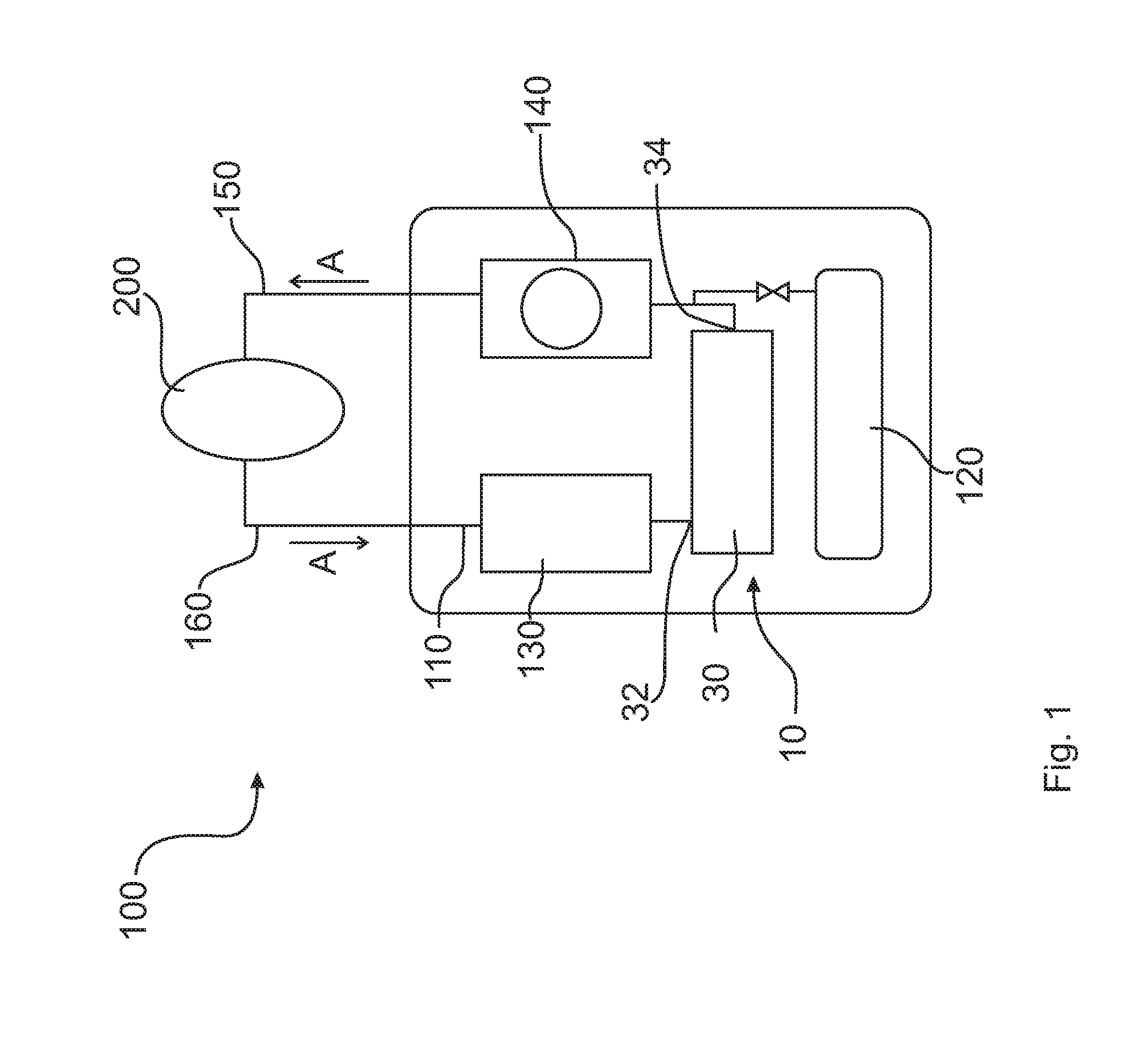
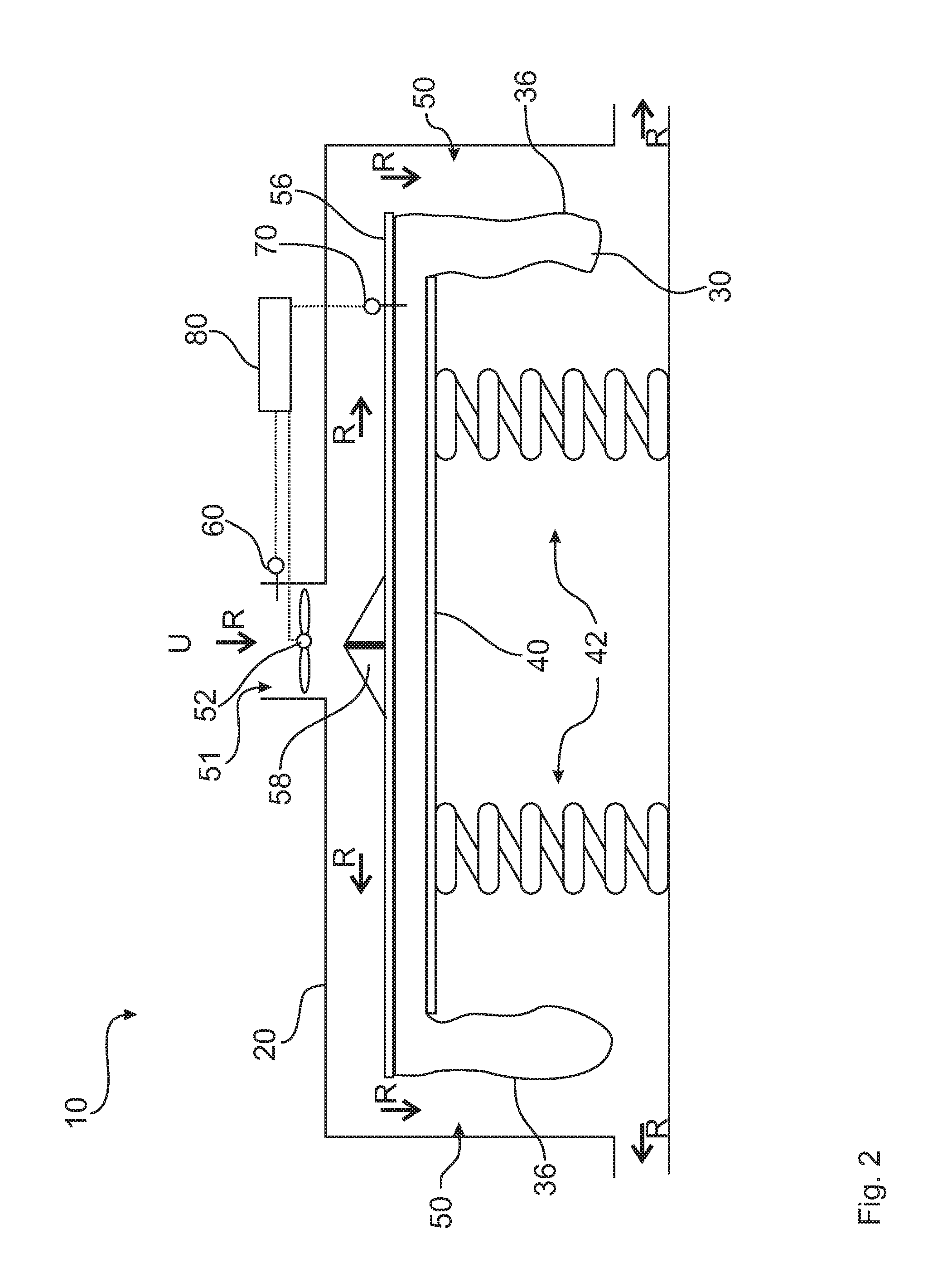
[0041]FIG. 1 diagrammatically shows a protective respiratory apparatus 100 in accordance with the invention. This has already been put into use by a person 200. Thus, a respiratory-air circuit 110 is provided which is described from the starting point of the person 200. When the person 200 expires air, the expired respiratory air A is introduced through an expiratory hose 160 along the respiratory-air circuit 110 into a respiratory-air regenerator 130. There, for example by means of absorption, a reduction in the CO2-content is effected. This step leads to a rise in temperature of the respiratory air A and in it being loaded with moisture. Subsequently, the warmed-up respiratory air A that is loaded with moisture can enter a respiratory bag (breathing bag) 30 along the respiratory-air circuit 110 through an inlet 32. Such a respiratory bag is formed as a cooling device 10 and will be explained further later in greater detail with reference to FIGS. 2 to 4. Downstream of the respirat...


PUM


Abstract

A cooling device (10), for a protective respiratory apparatus (100), has a housing (20), a breathing bag (30) arranged in the housing (20) with an inlet (32) for respiratory air (A) and an outlet (34) for cooled respiratory air (A) and a spring plate (40) with a spring device (42) to apply a spring force to the breathing bag (30). Between the housing (20) and at least one section of an outer side (36) of the breathing bag (30) an cooling air channel (50) is formed. The cooling air channel (50) is connected to the ambient air (U) outside the housing (20) in a fluid-communicating manner. A blower (52) is arranged for the generation of a flow of the ambient air (U) through the cooling air channel (50). Furthermore a protective respiratory apparatus (100) having such a cooling device is provided.

Description

CROSS REFERENCE TO RELATED APPLICATIONS[0001]This application is a United States National Phase Application of International Application PCT / EP2014 / 002667 filed Oct. 1, 2014 and claims the benefit of priority under 35 U.S.C. §119 of German Patent Application 10 2013 016 601.2 filed Oct. 7, 2013 the entire contents of which are incorporated herein by reference.FIELD OF THE INVENTION[0002]The present invention relates to a cooling device for a protective respiratory apparatus and also to a protective respiratory apparatus for the respiration of a person.BACKGROUND OF THE INVENTION[0003]Protective respiratory apparatuses for people are known in principle. They are used, for example, to supply relief forces in emergencies with atmospheric oxygen and corresponding respiratory air. Such protective respiratory apparatuses are, for example, portable systems so that relief forces, for example fire fighters, are supplied with respiratory air even in difficult and adverse ambient conditions.[0...

Claims


Application Information

Patent Timeline
Patent Type & Authority Applications(United States)
IPC IPC(8): A62B9/00
CPCA62B9/003A62B7/02A62B9/00
Inventor KOCH, JOCHIMSTEMICH, CARSTENWILKE, BASTIANULBRICH, CHRISTIAN
Owner DRAGER SAFETY
Why Eureka
Try Eureka