Idling stop control device

a technology of idling stop and control device, which is applied in the direction of engine starters, machines/engines, transportation and packaging, etc., can solve the problems of large electric power consumed by the activation unfavorable rolling motion state of the vehicle, and vehicle driver discomfort, etc., and achieve the effect of short activation time of the electric active stabilizer

Active Publication Date: 2016-09-01
TOYOTA JIDOSHA KK
View PDF8 Cites 4 Cited by
  • Summary
  • Abstract
  • Description
  • Claims
  • Application Information

AI Technical Summary

Benefits of technology

[0032]According to this aspect of the present specification, when the termination of the activation of the electric actuator is detected after the engine stop permission threshold is changed from the first threshold to the second threshold, the engine stop permission threshold is returned from the second threshold to the first threshold. Thereby, when the vehicle driver is unlikely to be subject to a discomfort due to a change of the motion state of the vehicle, advantageous effects such as a reduction of an amount of fuel consumed by the engine and a reduction of an amount of an exhaust gas discharged from the engine can be assuredly obtained by the execution of the idling stop control.
[0033]According to another aspect of the present specification, the electric actuator may be an electric active stabilizer that changes a torsional stiffness of a stabilizer bar by driving an electric motor.
[0034]According to this aspect of the present specification, when the electric active stabilizer starts to activate while the automatic engine stop control is not executed, the engine stop permission threshold is changed from the first threshold to the second threshold. Thereby, when the operation of the engine is automatically stopped during the activation of the electric active stabilizer, the remaining electric power amount index value of the battery is assuredly maintained at a value equal to or larger than the second threshold. As a result, it is possible to reduce a possibility that a rolling motion state of the vehicle undesirably changes and it is possible to prohibit the vehicle driver from being subject to a discomfort as possible. In particular, the electric active stabilizer operates during a turning of a body of the vehicle and thus, normally, the activation time of the electric active stabilizer is short. Therefore, it is possible to set the second threshold such that the remaining electric amount index value of the battery does not decrease to below the engine restart threshold during the activation of the electric active stabilizer.
[0035]Further, the electric active stabilizer may activate due to a disturbance occurring when vehicle travels on an uneven road. At this time, the electric active stabilizer activates independently of the vehicle drivers operation. When the execution of the automatic engine restart control of the idling stop control starts independently of the vehicle divers operation, the vehicle driver is likely to be subject to a discomfort, compared with when the execution of the automatic engine restart control starts is terminated by the vehicle drivers operation. Thus, when the operation of the engine restarts during the activation of the electric active stabilizer, the vehicle driver is likely to be subject to a discomfort. On the other hand, according to the another aspect of the present specification, it is possible to appropriately solve such a problem.
[0036]According to another aspect of the present specification, the electronic control unit is programmed to set the second threshold such that the second threshold set when a speed of the vehicle is large, is larger than the second threshold set when the speed of the vehicle is small.
[0037]When the vehicle travels at a high speed, a time of activation of the electric active stabilizer tends to increase or an amount of the electric power consumed by activation of the electric active stabilizer tends to increase. According to the another aspect of the present specification, the second threshold is set such that the second threshold set when the speed of the vehicle is large, is larger than the second threshold set when the speed of the vehicle is small. Thus, it is possible to further reduce a possibility that the starter activates during the activation of the electric active stabilizer.

Problems solved by technology

The electric active stabilizer temporarily operates, for example, when the vehicle turns, however, an amount of an electric power consumed by the activation of the electric active stabilizer is large.
At this time, the activation of the starter causes an amount of an electric power supplied to the electric active stabilizer to change and thus, causes the rolling motion state of the vehicle to undesirably change.
Therefore, the vehicle driver may be subject to a discomfort.
Such a problem raises in the electric active stabilizer as well as in the other electric actuators that change the motion state of the vehicle.
As a result, the motion state of the vehicle considerably changes and thus, the vehicle driver may be subject to a discomfort
Therefore, when the electric actuator activates, the automatic engine stop condition is unlikely to be satisfied.
In particular, the electric active stabilizer operates during a turning of a body of the vehicle and thus, normally, the activation time of the electric active stabilizer is short.
Further, the electric active stabilizer may activate due to a disturbance occurring when vehicle travels on an uneven road.
When the execution of the automatic engine restart control of the idling stop control starts independently of the vehicle divers operation, the vehicle driver is likely to be subject to a discomfort, compared with when the execution of the automatic engine restart control starts is terminated by the vehicle drivers operation.
Thus, when the operation of the engine restarts during the activation of the electric active stabilizer, the vehicle driver is likely to be subject to a discomfort.

Method used


Image

  • Idling stop control device
  • Idling stop control device
  • Idling stop control device

Examples


Embodiment Construction

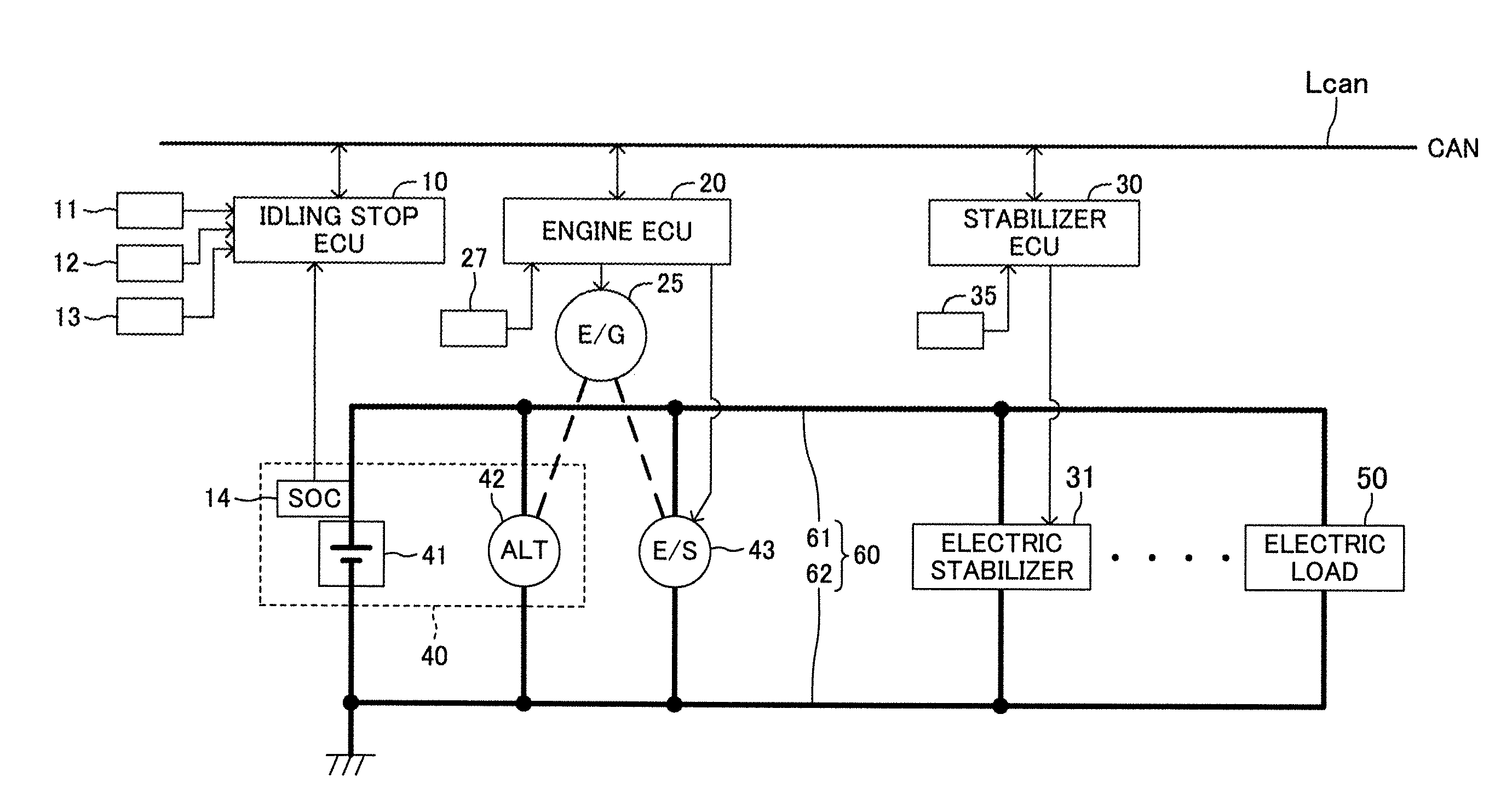
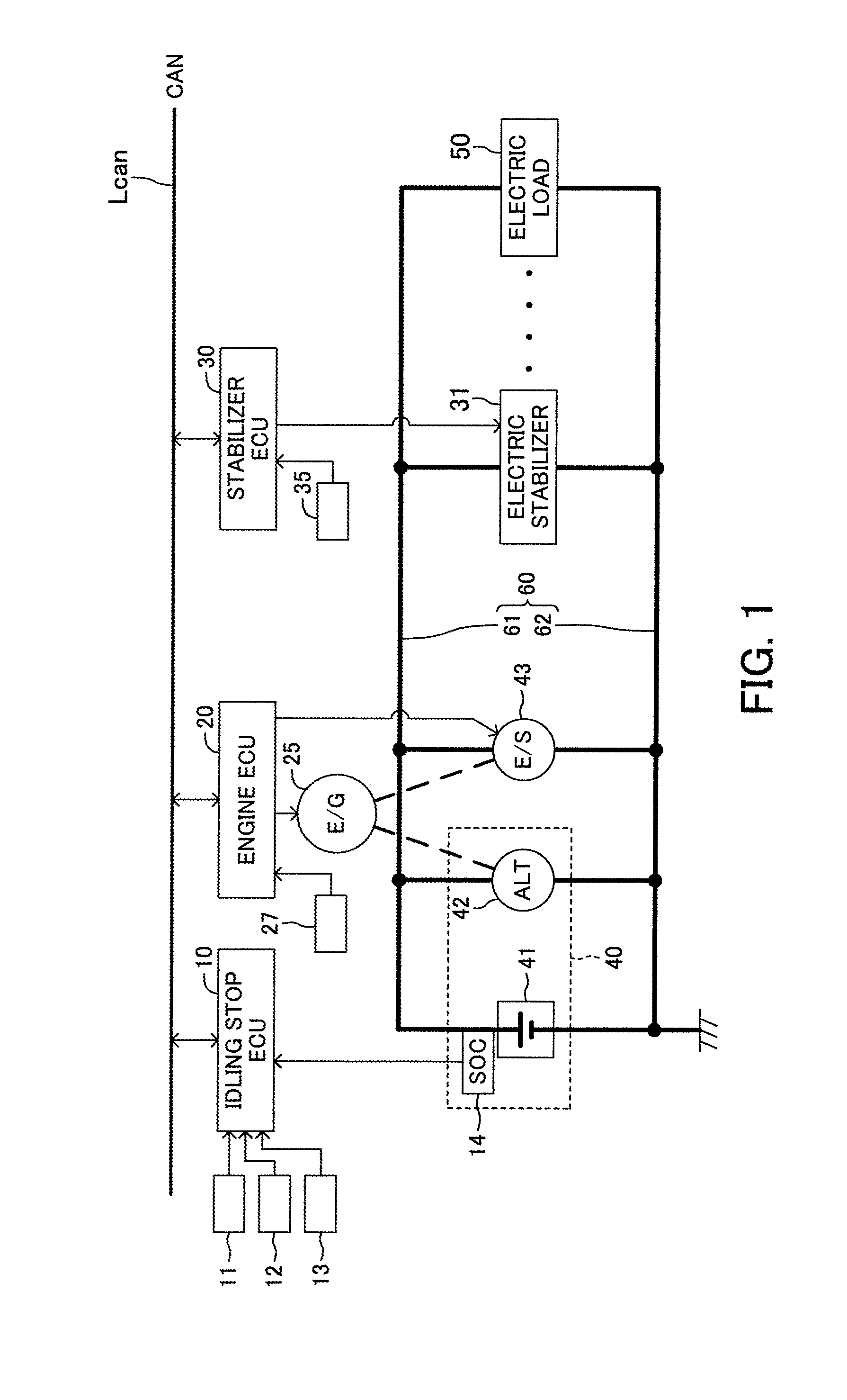
[0050]Below, an idling stop control device according to an embodiment of the present specification will be described with reference to the drawings. FIG. 1 shows a schematic configuration of an idling stop control device and a system relating to an operation of the idling stop control device. A vehicle (or an automobile) of the embodiment is a vehicle, which is configured to travel with wheels driven by an internal combustion engine. This vehicle does not include any electric drive source such as an electric motor that drives the vehicle.

[0051]This vehicle includes the idling stop control device having an idling stop electronic control unit 10. The idling stop electronic control unit 10 according to the embodiment executes an idling stop control that automatically stops an operation of an internal combustion engine 25 when an idling stop condition is satisfied during the stop of the vehicle as well as during the travelling of the vehicle. Hereinafter, the idling stop electronic cont...


PUM


Abstract

An electronic control device automatically stops an engine operation when a remaining electric power amount index value is equal to or larger than an engine stop permission threshold. The device automatically restarts the engine operation when the remaining electric power amount index value is smaller than an engine restart threshold after the engine operation is automatically stopped. The device changes the engine stop permission threshold from a first threshold, which has been set until a start of an activation of an electric actuator, to a second threshold, which is larger than the first threshold, when the automatic engine stop is not carried out and the activation of the actuator is detected.

Description

CROSS-REFERENCE TO RELATED APPLICATIONS[0001]This application claims priority to Japanese Patent Application No. 2015-036969, filed on Feb. 26, 2015, the entire contents of which are hereby incorporated by reference.BACKGROUND[0002]1. Technical Field[0003]The present specification relates to an idling stop control device which can save fuel and reduce an amount of an exhaust gas by automatically temporarily stopping an operation of an internal combustion engine.[0004]2. Description of the Related Art[0005]Conventionally, there is known a vehicle equipped with an idling stop control device that executes an idling stop control. In general, the idling stop control device automatically stops an operation of an internal combustion engine when the idling stop control device detects a stop of a vehicle on the basis of a speed of the vehicle (i.e., a vehicle speed) or an operation of a brake pedal or the like. On the other hand, the idling stop control device restarts the operation of the e...

Claims


Application Information

Patent Timeline
Patent Type & Authority Applications(United States)
IPC IPC(8): B60W30/192B60W30/02B60W10/06F02N11/08B60W20/40
CPCB60W30/192F02N11/0825B60W20/40B60W2520/04B60W30/025Y10S903/905B60W2510/244B60W10/06B60W10/22B60W30/18018B60W30/181B60W40/09B60W50/14B60W2050/0075B60W2520/10B60W2556/10F02N11/0818F02N11/0862F02N11/087F02N2200/061F02N2200/102Y02T10/40Y02T10/84
Inventor MAJIMA, HIROSHI
Owner TOYOTA JIDOSHA KK
Why Eureka
Try Eureka