
Apparatus and method for rapid deployment of a parachute

a technology of rapid deployment and parachute, which is applied in the field of parachutes, can solve the problems of excessive time needed for fully deploying such prior art equipment until the canopy is sufficiently inflated and expanded, and the delay corresponds to a significant drop of tens of meters

Active Publication Date: 2016-09-01
PARAZERO LTD
View PDF3 Cites 42 Cited by
  • Summary
  • Abstract
  • Description
  • Claims
  • Application Information

AI Technical Summary

Benefits of technology

The invention is a parachute system that can be quickly deployed in less than a second. This ensures that users can be protected even when jumping from a high building. The system uses a gas generator to trigger the parachute. The patent also describes how the parachute is designed to be sealingly engaged with a tube, which helps to ensure proper operation.

Problems solved by technology

Such a delay corresponds to a significant drop of tens of meters.
During an foreseen skyscraper related catastrophic event, such as an earthquake or a terroristic activity, people entrapped within the skyscraper generally do not have time enough to escape imminent danger by descending a stairwell to a plaza surrounding the building.
However, the time needed for fully deploying such prior art apparatus until the canopy is sufficiently inflated and expanded is excessive, precluding the use thereof for parachuting from a relatively low story of a building.
Also, the prior art apparatus is either heavy, complicated to deploy or expensive, and is therefore not suitable for large scale use during a catastrophic event.

Method used


Image

  • Apparatus and method for rapid deployment of a parachute
  • Apparatus and method for rapid deployment of a parachute
  • Apparatus and method for rapid deployment of a parachute

Examples


example

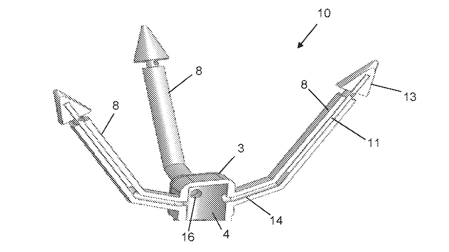
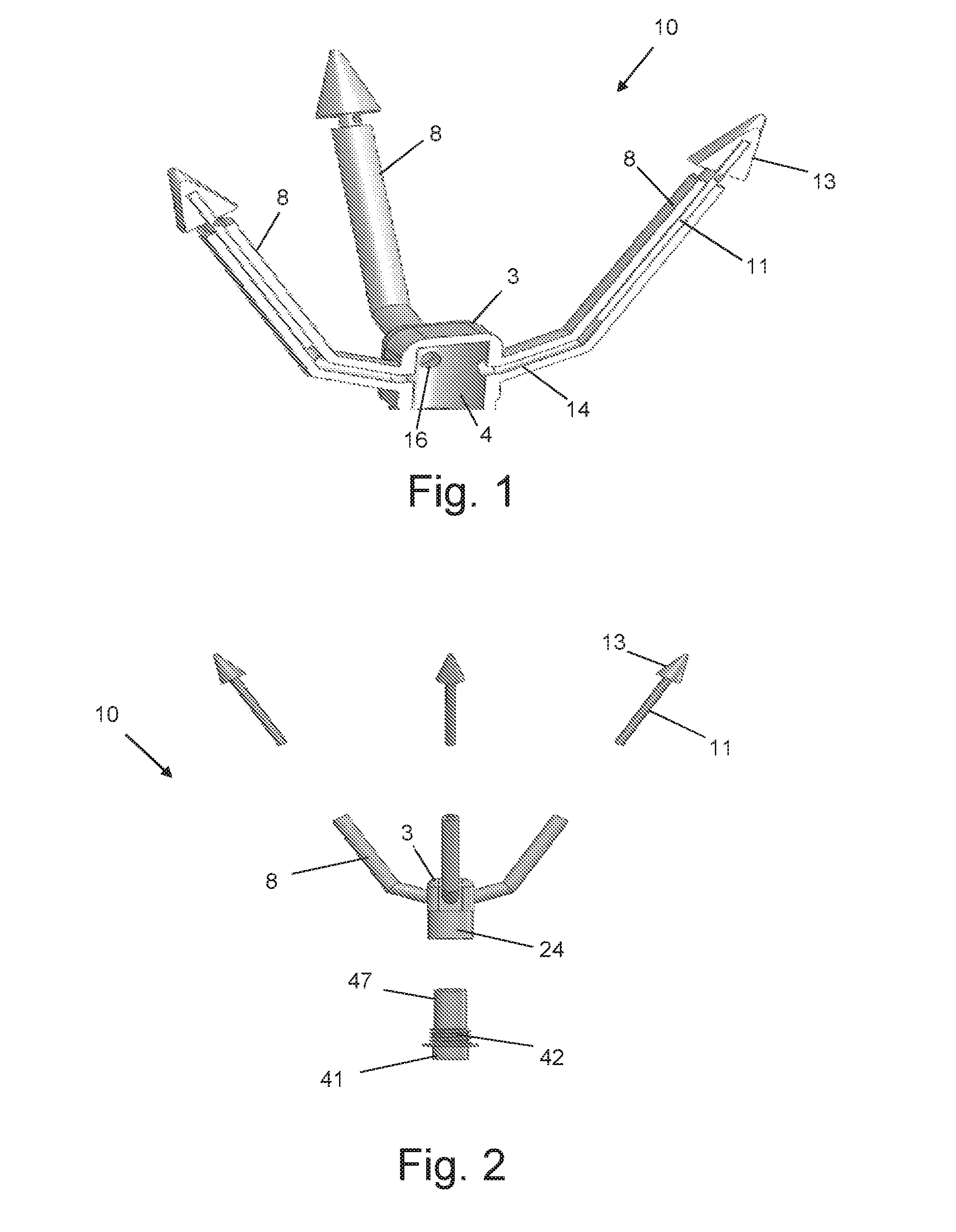
[0062]The parachute deploying apparatus weighing 450 gm was carried by a multi-rotor UAV having a weight of 7 kg, a diameter of 1.10 m and a height of 0.5 m. The canopy was made of Nylon 66 ripstop fabric, and had a diameter of 1.75 m. Six suspension lines, each having a length of 1.6 m, were connected to the aircraft. Three draw cords, each having a length of 25 cm, were connected to a corresponding projectile configured with an arrow-shaped head.

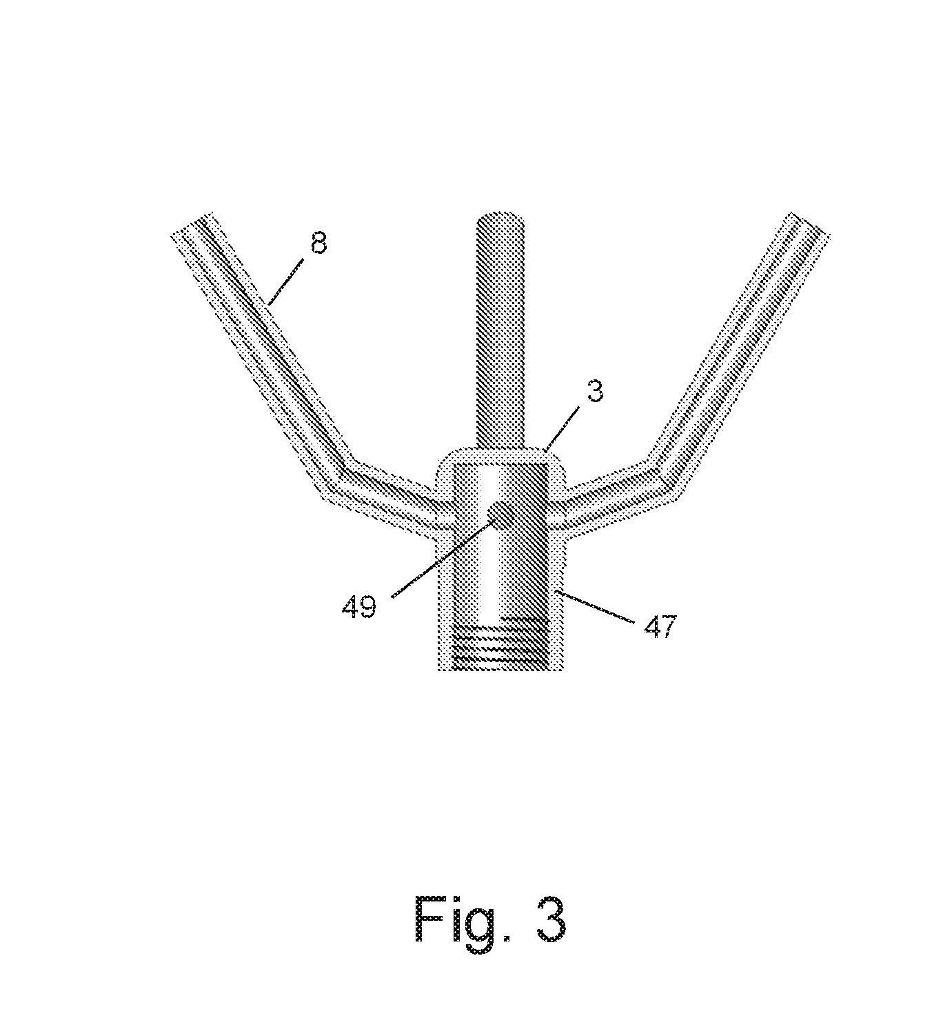
[0063]Three inclined tubes extended from the manifold. A projectile having a weight of 23 gm, and an arrow-shaped head connected to a rod having a length of 6 cm was inserted within a corresponding tube. Flexible polymeric material was applied to the tubes, providing sealing after insertion of the corresponding projectile therewithin.

[0064]The single MGG that was threadedly engageable with the manifold was the Autoliv A7Zr2.1, IMI-Type 610258300, manufactured by Autoliv, Ogden, Utah. The MGG had a diameter of 1.5 cm and a length of 4 cm. T...


PUM


Abstract

The present invention relates to a parachute deploying apparatus, comprising: a) a manifold with which is releasably coupled a single vessel within which pressurized gas is generated; b) a gas generator which cooperates with said vessel; c) a plurality of hollow tubes which extend obliquely and upwardly from, and are in communication with, said manifold; and d) a plurality of projectiles, each of which formed with a rod that is receivable in a corresponding tube and to each of which is connected a cord that is also connected to a corresponding portion of an undeployed parachute, wherein the pressurized gas which is generated upon triggering of said gas generator is flowable through each of said tubes to propel said plurality of projectiles in different directions and to cause said parachute to become deployed.

Description

FIELD OF THE INVENTION[0001]The present invention relates to the field of parachutes. More particularly, the invention relates to an apparatus and method for rapid deployment of a parachute.BACKGROUND OF THE INVENTION[0002]The deployment of a parachute according to prior art methods involves several steps, including a triggering action initiated by an operator or a user which causes the parachute canopy to be longitudinally extracted from the compartment in which it is stored, and a passive inflation process characterized by an influx of ambient air into the canopy which causes the latter to expand until achieving the desired canopy diameter. The canopy expansion is generally resisted by structural tension of the canopy fabric and by inertia, taking on the order of at least 5 seconds until fully expanded. Such a delay corresponds to a significant drop of tens of meters.[0003]During an foreseen skyscraper related catastrophic event, such as an earthquake or a terroristic activity, pe...

Claims


Application Information

Patent Timeline
IPC IPC(8): B64D17/72B64D17/76
CPCB64D17/76B64D17/725A62B1/22B64D17/72B64D17/80B64D45/00B64U70/83B64U2201/20B64U20/83A62B1/00
Inventor TSALIAH, AMIRKRAUSS, RAN
Owner PARAZERO LTD
Learn More