Retention device

a technology of a retention device and a spring element, which is applied in the direction of sustainable transportation, mechanical equipment, machines/engines, etc., can solve the problems of unpredictability of the radial force applied by the slider b>28/b>, the loss of lubricant between the mating faces, and the risk of damage, etc., to reduce the weight of the retention device and increase the stiffness of the spring elemen

Active Publication Date: 2016-09-01
ROLLS ROYCE PLC
View PDF1 Cites 3 Cited by
  • Summary
  • Abstract
  • Description
  • Claims
  • Application Information

AI Technical Summary

Benefits of technology

[0014]Movement of the spring element along the ramped surface allows adjustment of the spacing / height of the contact surface above the outer surface of the body and thus adjustment of the overall depth of the device. This means that the retention device can be inserted into the slot when having its minimum depth so that marking and damage of the device and component is minimised. This insertion no longer requires use of an impact tool. The device can then be adjusted by sliding of the mounting portion of the spring element over the ramp surface towards the upper end to increase the spacing / height of the contact surface above the outer surface of the body until the contact surface contacts the component and applies the desired radial force. The radial force can be selected to take account of manufacturing tolerances by selecting an appropriate sliding distance of the mounting portion along the ramp surface.
[0025]Where the recess is defined by lateral recess walls, some embodiments may comprise a laterally extending transverse undercut in at least one or both of the lateral recess walls proximal the first lateral end of the body e.g. extending from the transversely-enlarged portion. The transverse undercut(s) may have an incline matching that of the first ramped surface. In these embodiments, the spring element may have comprise at least one (e.g. two opposing) transverse lug(s) for location and sliding within the undercut(s). This secures the spring element within the recess.
[0026]In some embodiments, the recess is defined only by transverse recess walls and the recess extends to the lateral edges of the body. In these embodiments, the spring element may have a transverse dimension substantially matching the transverse dimension of the body. This allows a larger transverse cross-sectional profile of the spring element which allows increased stiffness of the spring element.
[0027]In some embodiments, the outer surface of the body comprises one or more cavities (which may cooperate with the recess) for reducing the weight of the retention device.
[0029]In some embodiments, the actuator comprises a first threaded portion and the body comprises a threaded hole extending from the first lateral end of the body into the recess. In this way, rotational movement of the actuator and engagement between the first threaded portion of the actuator and the threaded hole effects controlled movement of the spacer portion along the ramp surface(s).

Problems solved by technology

This unconstrained movement can lead to fretting between the fan blade roots 27 and slots 26, which causes loss of the lubricant between the mating faces.
There is therefore a risk of damage, if not actual damage, every time the engine is shut down or started.
Another problem with the known devices is that the spring 29 is fixed and thus radial force applied to the blade root 27 depends only on the distance between the blade root 27 and the radially inner surface of the slot 26.
This distance is subject to manufacturing tolerances and thus the radial force applied by the slider 28 is subject to unpredictability.

Method used


Image

  • Retention device
  • Retention device
  • Retention device

Examples


first embodiment

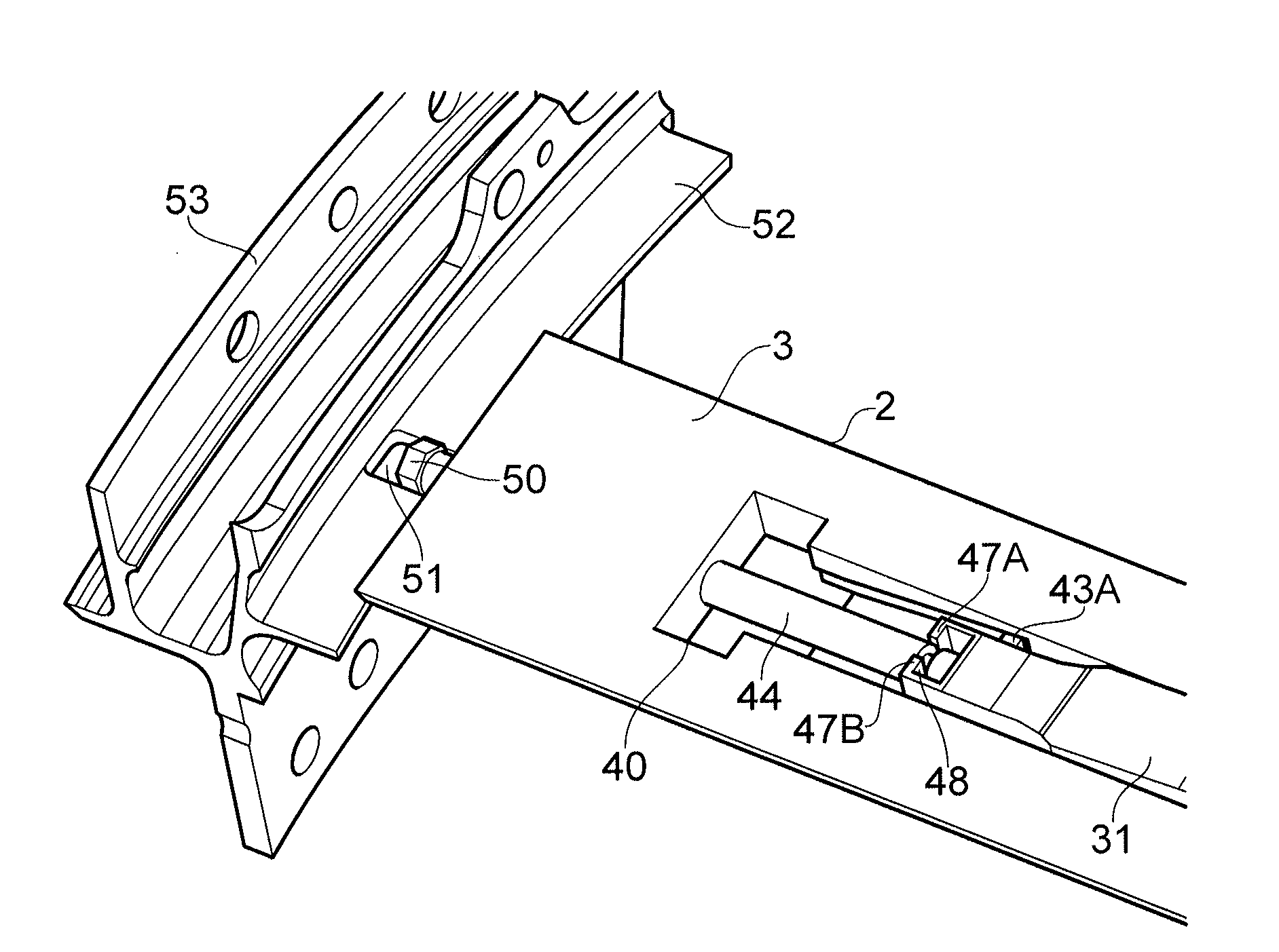
[0055]As shown in FIGS. 4 to 7, the present invention provides a retention device 1 for applying a radial force to a component such as a rotor blade (not shown) held within a slot in a rotor disc.

[0056]The device 1 comprises a body 2 having an outer surface 3 for facing the component. The outer surface 3 has a recess 4 having a recess base 5.

[0057]The recess base comprises a first ramped surface 6A extending from a lower end 7A to an upper end 8A. The recess base further comprises a second ramped surface 6B extending from a lower end 7B to an upper end 8B. The first and second ramp surfaces 6A, 6B extend laterally / axially within the recess 4 with both lower ends 7A, 7B of the ramp surfaces 6A, 6B proximal a first lateral end 9 of the body 2 and both upper ends 8A, 8B distal the first lateral end 9 of the body 2. The lower end 7B of the second ramp surface 6B is proximal the upper end 8A of the first ramp surface 6A. The first and second ramp surfaces 6A, 6B have the same incline.

[00...

second embodiment

[0075]FIG. 8 shows the present invention in which the first and second ramp surfaces 6A′, 6B′ extend laterally, parallel to one another across the recess 4′ with both lower ends 7A′, 7B′ of the ramp surfaces 6A′, 6B′ located proximal the first lateral end 9′ of the body 2′.

[0076]The recess 4′ is defined by transverse end walls 54A, 54B and extends to the transverse edges of the body 2′ (i.e. there are no laterally extending walls defining the recess). The recess base 5′ further comprises a channel 55.

[0077]The outer surface 3′ of the body 2′ further comprises two cavities 56A, 56B extending laterally either side of the recess 4′. This is to reduce the amount of material and hence the weight of the retention device.

[0078]The spring element 30′ has a transverse dimension that substantially matches the transverse dimension of the body 2′. This allows a larger transverse cross-sectional profile and increased stiffness of the spring element 30′.

[0079]The spring element 30′ has two downwa...


PUM


Abstract

The present invention provides a retention device for applying a radial force to a component (e.g. a rotor blade) within a slot (e.g. on a rotor disc). The device comprises a body having an outer surface for facing the component. The outer surface comprises a recess having a recess base with a first ramped surface extending from a lower end proximal a first lateral end of the body to an upper end. The device further comprises a spring element having a contact surface for contacting the component and a first mounting portion for mounting the spring element on the first ramped surface such that the first mounting portion is slidable along the first ramped surface towards the upper end to increase the spacing of the contact surface above the outer surface of the body.

Description

FIELD OF THE INVENTION[0001]The present invention relates to a retention device, for example, a retention device for restraining a component such as a fan blade by applying a radial force.BACKGROUND OF THE INVENTION[0002]With reference to FIG. 1, a ducted fan gas turbine engine is generally indicated at 10 and has a principal and rotational axis X-X. The engine comprises, in axial flow series, an air intake 11, a propulsive fan 12, an intermediate pressure compressor 13, a high-pressure compressor 14, combustion equipment 15, a high-pressure turbine 16, an intermediate pressure turbine 17, a low-pressure turbine 18 and a core engine exhaust nozzle 19. A nacelle 21 generally surrounds the engine 10 and defines the intake 11, a bypass duct 22 and a bypass exhaust nozzle 23.[0003]During operation, air entering the intake 11 is accelerated by the fan 12 to produce two air flows: a first air flow A into the intermediate pressure compressor 13 and a second air flow B which passes through ...

Claims


Application Information

Patent Timeline
Patent Type & Authority Applications(United States)
IPC IPC(8): F01D5/32F01D5/12F01D5/30F01D5/02
CPCF01D5/326F01D5/02F01D5/12F01D5/3007F05D2260/30F05D2230/60F05D2240/30F05D2240/24F05D2220/32F01D5/323Y02T50/60
Inventor EVANS, DALEVILLANUEVA, ALFONSO
Owner ROLLS ROYCE PLC
Why Eureka
Try Eureka