

Lighting device and luminaire
- Summary
- Abstract
- Description
- Claims
- Application Information
AI Technical Summary
Benefits of technology
Problems solved by technology
Method used
Image

Examples
Embodiment Construction
[0036]It should be understood that the FIG.s are merely schematic and are not drawn to scale. It should also be understood that the same reference numerals are used throughout the FIG.s to indicate the same or similar parts.
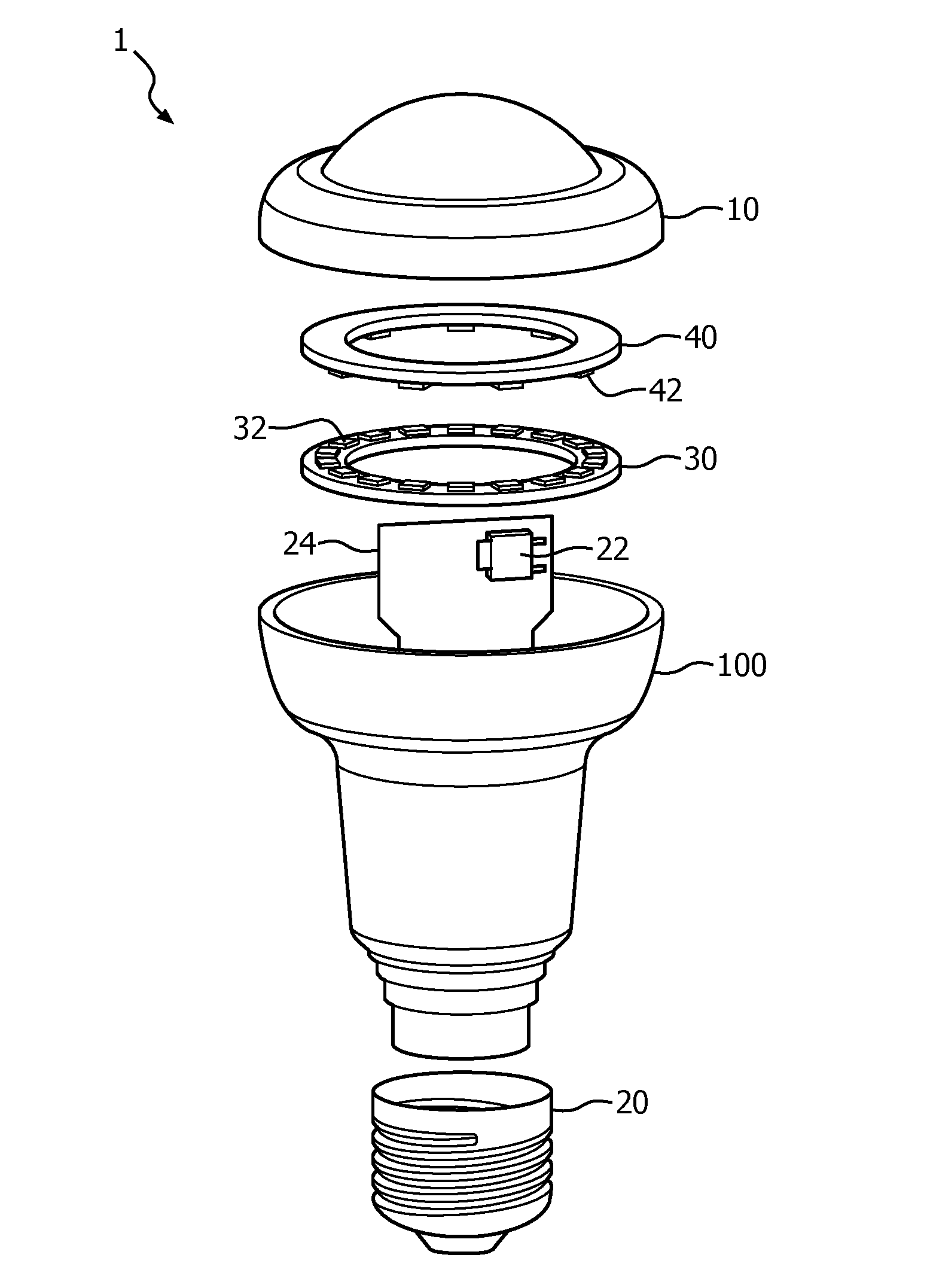
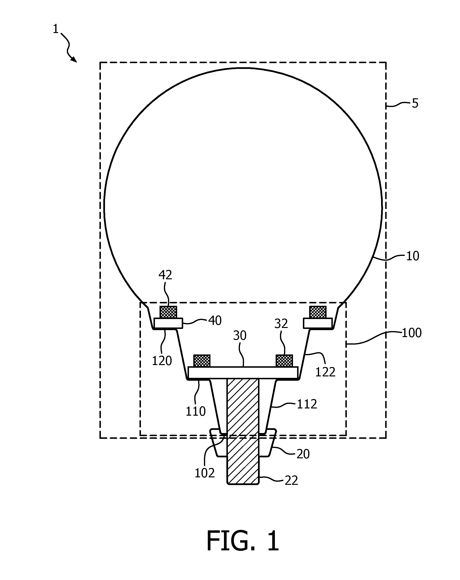
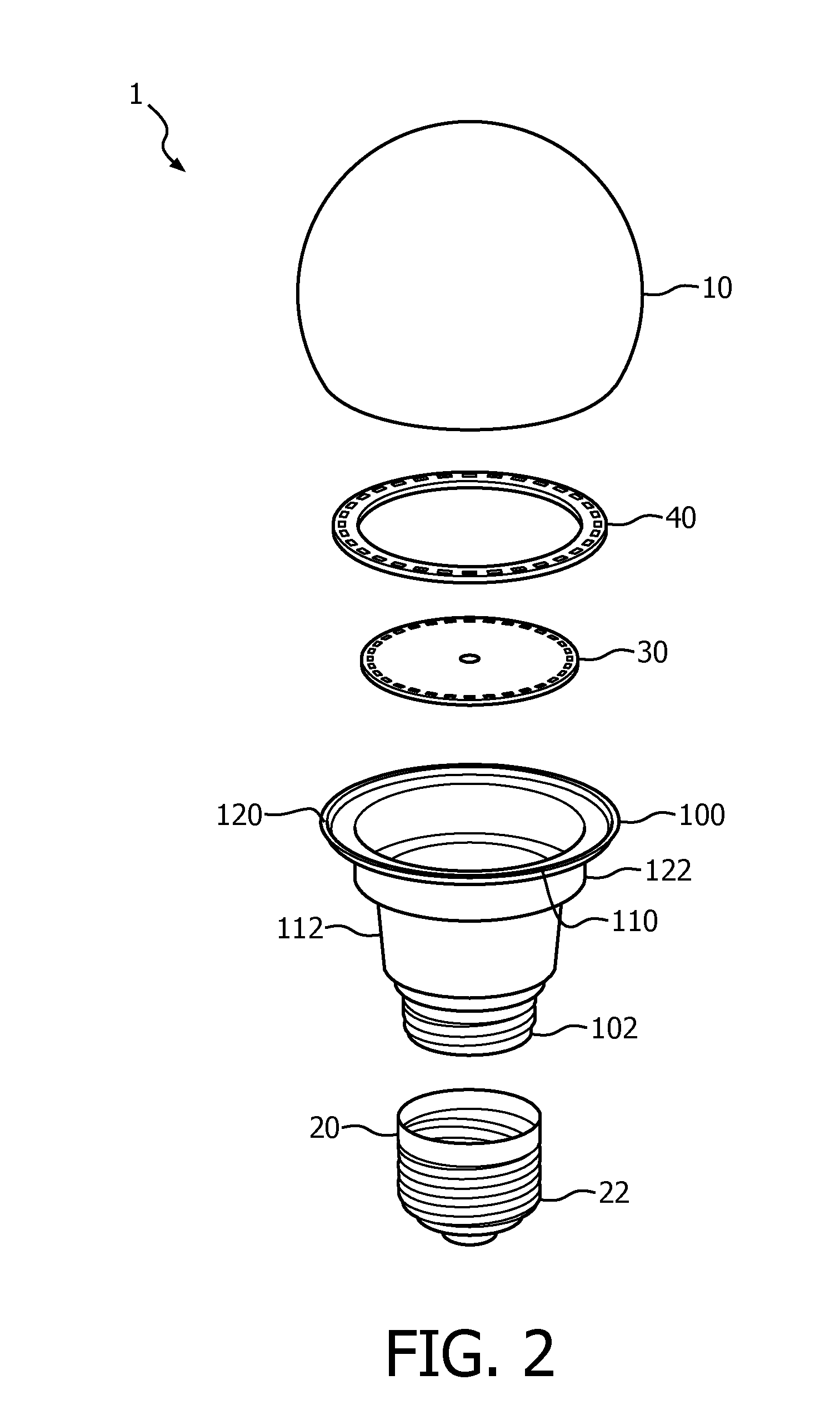
[0037]The present invention is based on the insight that a lighting device comprising a bulbous body, e.g. a light bulb, which lighting device comprises SSL elements, can be designed to include a plurality of tiers or steps at least including a first step and a second step on an inner surface of the bulbous body, which tiers can be spaced apart, i.e. axially displaced relative to each other along the central axis of the lighting device, such that the lighting device can produce a highly homogeneous luminous output such as an Energy Star-compliant luminous output.
[0038]Moreover, the need for a heat sink may be avoided as the bulbous body can be used to effectively dissipate the heat generated by the SSL elements. In some embodiments of the present invention, at le...
PUM
| Property | Measurement | Unit |
|---|---|---|
| Diameter | aaaaa | aaaaa |
| Transparency | aaaaa | aaaaa |
Abstract
Description
Claims
Application Information