Cold storage heat exchanger

a heat exchanger and cold storage technology, applied in indirect heat exchangers, lighting and heating apparatus, transportation and packaging, etc., can solve the problems of increasing increasing the pressure loss in the tube adjacent to the cold storage material container, and affecting the cooling effect of the cooling effect, so as to achieve the effect of improving the cooling effect and easy cooling

Active Publication Date: 2016-09-01
DENSO CORP +1
View PDF2 Cites 8 Cited by
  • Summary
  • Abstract
  • Description
  • Claims
  • Application Information

AI Technical Summary

Benefits of technology

[0007]In view of the above points, it is an object of the present disclosure to provide a cold storage heat exchanger that may improve cold storage performance.
[0009]Accordingly, by disposing the reduction unit in the distribution tank unit to reduce the passage cross-sectional area of the coolant passage in the distribution tank unit, coolant may be held back at the reduction unit. Then, among the plurality of tubes, the cold storage material container is joined to a tube disposed upstream in a coolant flow direction from the reduction unit in the coolant passage, therefore the coolant held back at the reduction unit flows more easily into the tube joined to the cold storage material container. For this reason, the flow rate of coolant flowing through the tube joined to the cold storage material container may be increased, and cold storage performance may be improved.
[0011]Accordingly, by disposing the large channel tube in which the passage cross-sectional area of the coolant passage is greater than the other tubes, coolant flows more easily into the large channel tube. Then, because the cold storage material container is joined to the large channel tube, the flow rate of coolant flowing through the tube joined to the cold storage material container may be increased, and cold storage performance may be improved.

Problems solved by technology

However, when storing cold energy to the cold storage material, the coolant in the tube, which is adjacent to the cold storage material container, evaporates and a pressure loss in the tube increases.
For this reason, even if it is desirable to quickly complete storing cold energy into the cold storage material, during the cold storage process, the pressure loss in the tube adjacent to the cold storage material container increases, and it becomes difficult for the coolant to flow.
As a result, there is a concern that cold storage performance may decrease.
If paraffin or the like is used as the cold storage material such that latent heat of fusion during phase change of the paraffin is used to store cold energy, a large transfer of heat occurs near the melting point of the cold storage material, and the reduction in cold storage performance becomes particularly noticeable.

Method used


Image

  • Cold storage heat exchanger
  • Cold storage heat exchanger
  • Cold storage heat exchanger

Examples


first embodiment

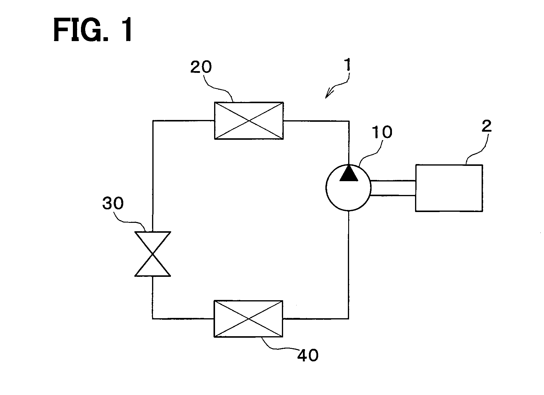
[0033]The configuration of a refrigeration cycle device that constitutes a vehicular air conditioning device according to a first embodiment of the present disclosure is shown in FIG. 1. A refrigeration cycle device 1 that constitutes this air conditioning device includes a compressor 10, a radiator 20, a decompressor 30, and an evaporator 40. These components are connected in a cycle by piping, and form a cooling circulation path.

[0034]The compressor 10 is driven by a power source 2 that drives the vehicle. The power source 2 is an internal combustion engine (or electric motor, etc.). When the power source 2 stops, the compressor 10 also stops. The compressor 10 draws coolant from the evaporator 40, compresses the coolant, and then discharges the coolant to the radiator 20. The radiator 20 cools the high temperature coolant. The radiator 20 is also referred to as a condenser. The decompressor 30 decompresses the coolant which was cooled by the radiator 20. The evaporator 40 causes ...

second embodiment

[0066]Next, a second embodiment of the present disclosure will be explained with reference to FIG. 6. When compared to the first embodiment described above, the present embodiment is different in that a protruding portion 52, which is described later, is disposed in the second distribution tank unit 420.

[0067]As shown in FIG. 6, the second distribution tank unit 420 respectively includes a protruding portion 52 that protrudes inward of each tank from the inner circumference surface of a wall portion 400 that forms the coolant passage in the second distribution tank unit 420. According to the present embodiment, the protruding portion 52 is disposed over the entire circumference of the each second distribution tank unit 420. Specifically, the protruding portion 52 is formed by indenting over the entire circumference of the outer circumferential surface of the wall portion 400 of the second distribution tank 420, so that the inner circumferential surface of the wall portion 400 protru...

third embodiment

[0075]Next, a third embodiment of the present disclosure will be explained with reference to FIG. 7. When compared to the above described first embodiment, the tubes 45 of the third embodiment have a different shape.

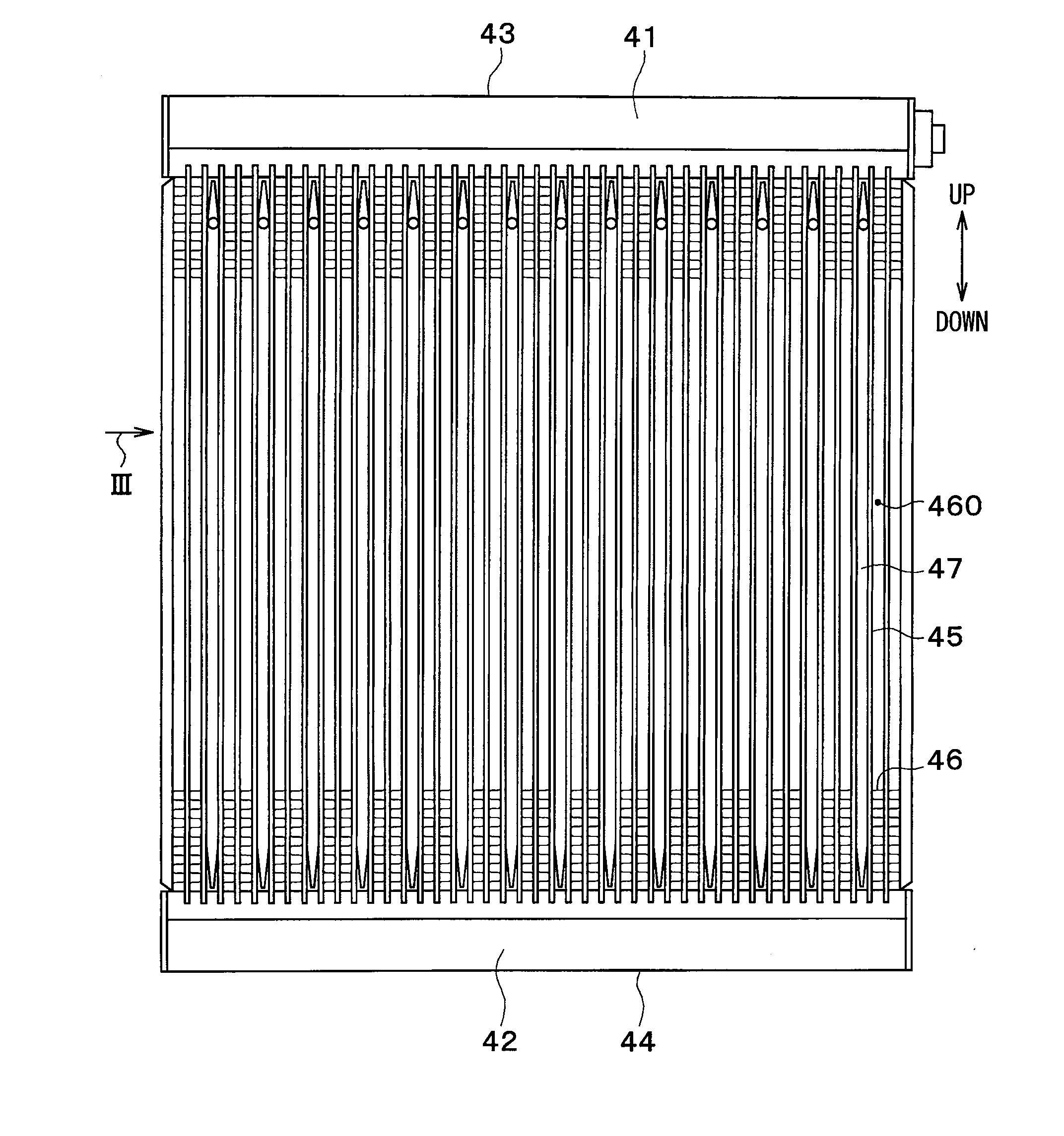
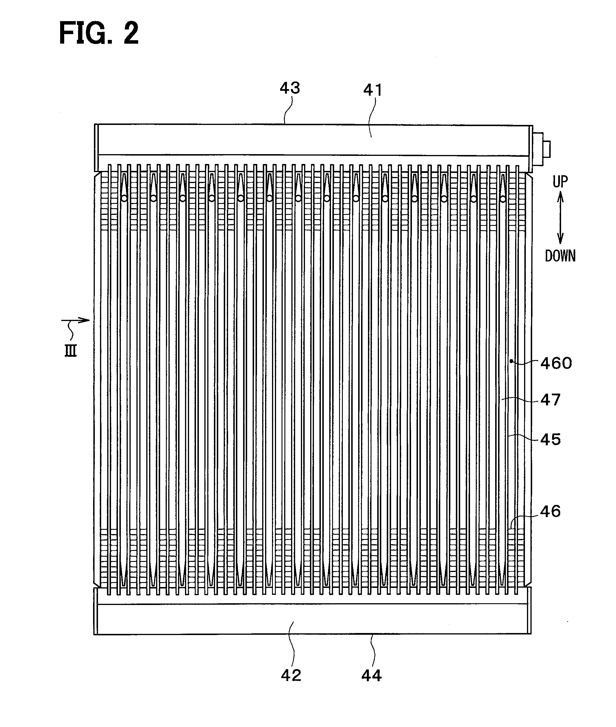
[0076]A length, in the lengthwise direction of the tubes 45, of the portion of the tubes 45 disposed inside the first to fourth distribution tank units 410, 420, 431, 440 is referred to as a protruding length. As shown in FIG. 7, the plurality of tubes 45 in communication with each of the second distribution tank unit 420 and the fourth distribution tank unit 440, which are positioned below the tubes 45 in the vertical direction, include a protruding tube 452 that has a longer protruding length than the other tubes 45. Further, FIG. 7 only shows the second distribution tank unit 420. The protruding tube 452 disposed in the fourth distribution tank unit 440 is the same as the protruding tube 452 disposed in the second distribution tank unit 420, and thus the illustration ...


PUM


Abstract

A cold storage heat exchanger includes a plurality of tubes, a coolant flowing in the tubes, a cold storage material container joined to the tubes, the cold storage material container defining a room that houses a cold storage material, and a distribution tank unit that distributes the coolant to the tubes. A coolant passage is formed in the tubes and the distribution tank unit. The distribution tank unit includes an aperture plate that reduces a passage cross-sectional area of the coolant passage. Among the plurality of tubes, the cold storage material container is joined to at least a tube disposed upstream in a coolant flow direction from the aperture plate in the coolant passage. Accordingly, cold storage performance may be improved.

Description

CROSS-REFERENCE TO RELATED APPLICATION[0001]The present application is based on Japanese patent application No. 2013-197882 filed on Sep. 25, 2013, the content of which is incorporated herein by reference.TECHNICAL FIELD[0002]The present disclosure relates to a cold storage heat exchanger used in a refrigeration cycle device.BACKGROUND ART[0003]Conventionally, a refrigeration cycle device is used in an air conditioning device. There have been attempts to provide limited cooling even when this refrigeration cycle device is in a stopped state. For example, in a vehicular air conditioning device, a compressor of a refrigeration cycle device is driven by a driving engine. For this reason, if the engine is stopped while the vehicle is temporarily parked, then the refrigeration cycle device stops. In order to provide limited cooling during this temporary parking, a cold storage heat exchanger is known, in which a cold storage material that stores cold energy is added to the refrigeration ...

Claims


Application Information

Patent Timeline
Patent Type & Authority Applications(United States)
IPC IPC(8): F25B39/00B60H1/32F28D1/053F28F9/02F28F1/12F28D20/02
CPCF25B39/00F28F1/126F28D20/021F28D1/05391F28F2275/04B60H1/3227F25B39/02F25B2400/24F28D2020/0013F28F9/028B60H1/00335B60H1/005F25B2500/18F28D20/0034Y02E60/14
Inventor ABEI, JUNNAKAMURA, TOMOHIKOFUTAMATA, HIROFUMIKITOU, YUUSUKENAGASAWA, TOSHIYA
Owner DENSO CORP
Why Eureka
Try Eureka