Evaporator

a technology of evaporator and evaporator chamber, which is applied in the direction of indirect heat exchangers, refrigeration components, lighting and heating apparatus, etc., can solve the problems of large amount of heat taken from cold storage materials, insufficient cold storage in cold storage mechanisms, and inability to control the temperature rise of air blown into the vehicle interior from air conditioning apparatuses. to prevent the adhesion of frost and reduce the energy needed

Active Publication Date: 2020-06-09
DENSO CORP
View PDF62 Cites 2 Cited by
  • Summary
  • Abstract
  • Description
  • Claims
  • Application Information

AI Technical Summary

Benefits of technology

[0010]During a normal operation that is not the idle stop state, the compressor of the air conditioning apparatus may be operated intermittently rather than continuously. Such an intermittent operation is carried out for, for example, the purpose of limiting a temperature decrease of the evaporator to prevent the adhesion of frost, or the purpose of reducing energy necessary for the operation of the compressor and realizing energy saving, for example.
[0012]Therefore, it is conceivable to increase a cold storage and release performance of the cold storage mechanism. The cold storage and release performance is the degree of heat transfer when the cold storage mechanism exchanges heat with the outside portion, that is, a magnitude of heat conduction or heat transfer between the cold storage mechanism and the outside portion. When the cold storage-and-release performance of the cold storage mechanism is increased, a large amount of heat is taken from the cold storage material within a short period of time during the operation of the compressor. For that reason, even when the intermittent operation as described above is performed, the cold storage material sufficiently lowers the temperature and solidifies. As a result, in a period in which the idle stop is not being performed (i.e. during the intermittent operation), the temperature rise of the air blown into the vehicle interior is controlled.
[0013]However, when the engine becomes in the idle stop state, a large amount of heat is added to the cold storage material within a short period of time (because the cold storage and release performance of the cold storage mechanism is high), and all of the cold storage material is melted immediately. For that reason, the temperature of the air blown into the vehicle interior is low immediately after the engine has put into the idle stop state, but the temperature immediately rises.
[0021]In the second cold storage mechanism having a relatively high heat storage-and-radiation performance, the temperature of the cold storage material lowers in a short period of time during which the compressor operates during the intermittent operation of the compressor. For that reason, since at least the second cold storage mechanism performs sufficient cold storage, the increase in the temperature of the air blown into the vehicle interior is limited.

Problems solved by technology

In this case, since the period during which the cold storage material is cooled is relatively short with the result that the cold storage material is not completely solidified, cold storage in the cold storage mechanism is not sufficiently performed.
As a result, the temperature rise of the air blown into the vehicle interior from the air conditioning apparatus cannot be controlled.
When the cold storage-and-release performance of the cold storage mechanism is increased, a large amount of heat is taken from the cold storage material within a short period of time during the operation of the compressor.
However, when the engine becomes in the idle stop state, a large amount of heat is added to the cold storage material within a short period of time (because the cold storage and release performance of the cold storage mechanism is high), and all of the cold storage material is melted immediately.
In this way, it is difficult to control the temperature rise of the air during the intermittent operation of the compressor while controlling the temperature rise of the air after transition to the idle stop state.
For that reason, an increase in the temperature of the air after transition to the idle stop state can be limited over a long period of time.
For that reason, since at least the second cold storage mechanism performs sufficient cold storage, the increase in the temperature of the air blown into the vehicle interior is limited.

Method used


Image

  • Evaporator
  • Evaporator
  • Evaporator

Examples


first embodiment

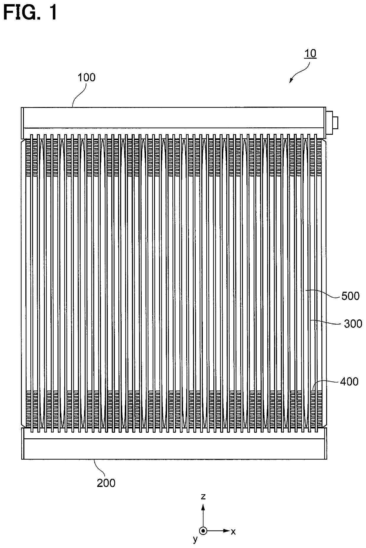
[0055]A first embodiment of the present disclosure will be described with reference to FIGS. 1 to 5. An evaporator 10 shown in FIG. 1 is an evaporator (evaporator) forming a part of a refrigeration cycle (not shown) configured as a vehicle air conditioning system. Refrigerant is sent to the evaporator 10 by a compressor not shown disposed in a part of the refrigeration cycle. The compressor operates by a driving force of an internal combustion engine installed in a vehicle. The evaporator 10 performs heat exchange between a refrigerant and air while internally evaporating a fed refrigerant, to thereby cool the air.

[0056]A configuration of the evaporator 10 will be described with reference to FIG. 1. The evaporator 10 includes an upper tank 100, a lower tank 200, tubes 300, corrugated fins 400, and cold storage mechanisms 500.

[0057]The upper tank 100 is a container for temporarily storing the refrigerant supplied to the evaporator 10 and supplying the refrigerant to the tubes 300. Th...

second embodiment

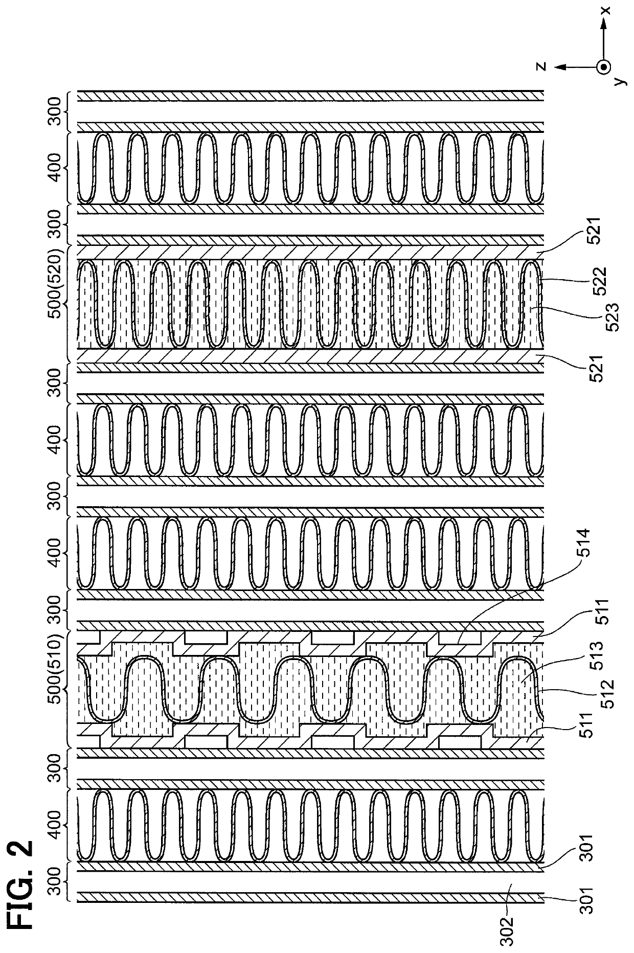
[0100]Hereinafter, a second embodiment of the present disclosure will be described with reference to FIG. 6. The second embodiment is different in only a configuration of a second cold storage mechanism 520 from the first embodiment, and the other configurations are identical with those in the first embodiment. FIG. 6 shows an internal structure of a cold storage material and the like.

[0101]In the present embodiment, a shape of a cold storage container 521 is the same as the shape of a cold storage container 511. In the cold storage container 521, multiple concave portions 524 retreating inward are provided. Portions of an outer surface of the cold storage container 521 other than the concave portions 524 abut against tubes 300.

[0102]In the inside of the cold storage container 521, the apexes of wavy inner fin 522 abut against and brazed to the inner wall surface of the cold storage container 521, more specifically, the inner wall surface of the concave portions 524. A pitch of the ...

third embodiment

[0109]Hereinafter, a third embodiment of the present disclosure will be described with reference to FIG. 9. Similarly, the third embodiment is different in only a configuration of a second cold storage mechanism 520 from the first embodiment, and the other configurations are identical with those in the first embodiment. FIG. 9 shows an internal structure of a cold storage material and the like.

[0110]In the present embodiment, a pitch of an inner fin 522 in the second cold storage mechanism 520 is the same as the pitch of an inner fin 512 in a first cold storage mechanism 510. In other words, the second cold storage mechanism 520 is different from the first cold storage mechanism 510 only in a contact area between a cold storage container 521 and a tube 300. Even in such a configuration, the same advantages as those in the first embodiment are obtained.

[0111]As a specific configuration for setting the contact area between the cold storage container 521 and the tube 300 to be larger t...


PUM


Abstract

An evaporator includes multiple cold storage mechanisms for lowering a temperature of a cold storage material housed inside a cold storage container by heat exchange with a refrigerant. The multiple cold storage mechanisms include a first cold storage mechanism and a second cold storage mechanism higher in heat storage-and-radiation performance than the first cold storage mechanism.

Description

CROSS REFERENCE TO RELATED APPLICATIONS[0001]This application is a U.S. National Phase Application under 35 U.S.C. 371 of International Application No. PCT / JP2016 / 002097 filed on Apr. 19, 2016 and published in Japanese as WO 2016 / 174852 A1 on Nov. 3, 2016. This application is based on and claims the benefit of priority from Japanese Patent Applications No. 2015-092589 filed on Apr. 30, 2015, and No. 2016-079306 filed on Apr. 12, 2016. The entire disclosures of all of the above applications are incorporated herein by reference.TECHNICAL FIELD[0002]The present disclosure relates to an evaporator that cools air by heat exchange with a refrigerant passing through an inside of the evaporator.BACKGROUND ART[0003]An evaporator used as a part of a refrigeration cycle in an air conditioning apparatus evaporates a liquid phase refrigerant inside the air conditioning apparatus to lower a temperature of the refrigerant, and thereby cools the air by heat exchange with the refrigerant.[0004]In th...

Claims


Application Information

Patent Timeline
Patent Type & Authority Patents(United States)
IPC IPC(8): F28F1/12F28D21/00F28D20/00F28D1/053F28F1/40F28D20/02F25B39/02B60H1/00
CPCF25B39/02F28F1/40B60H1/005F28D20/02F28D1/05366F28F1/126B60H1/00335F28D20/026F28D2021/0085Y02E60/145F28D2020/0013Y02E60/14
Inventor KITOU, YUUSUKEABEI, JUNKAWACHI, NORIHIDETORIGOE, EIICHICHATANI, SHOTA
Owner DENSO CORP
Why Eureka
Try Eureka