
Operation device and operation method

a technology of operation device and operation method, which is applied in the direction of domestic stoves or ranges, lighting and heating apparatus, instruments, etc., can solve the problems of difficulty for users in power setting, and achieve the effect of enhancing the usability of users

Active Publication Date: 2016-09-01
PANASONIC INTELLECTUAL PROPERTY MANAGEMENT CO LTD
View PDF7 Cites 73 Cited by
  • Summary
  • Abstract
  • Description
  • Claims
  • Application Information

AI Technical Summary

Benefits of technology

The invention is an operation device and method that make it easy for users to set the power and time settings for their household appliance. This improves the user experience and makes the device more user-friendly.

Problems solved by technology

However, it is difficult for the user to perform power settings such as adjustment of heating power or output of microwave, and time settings with a simplified operation and with a less number of operations when the user uses the oven function or the microwave function of manual operations of a cooking heater.

Method used


Image

  • Operation device and operation method
  • Operation device and operation method
  • Operation device and operation method

Examples


first embodiment

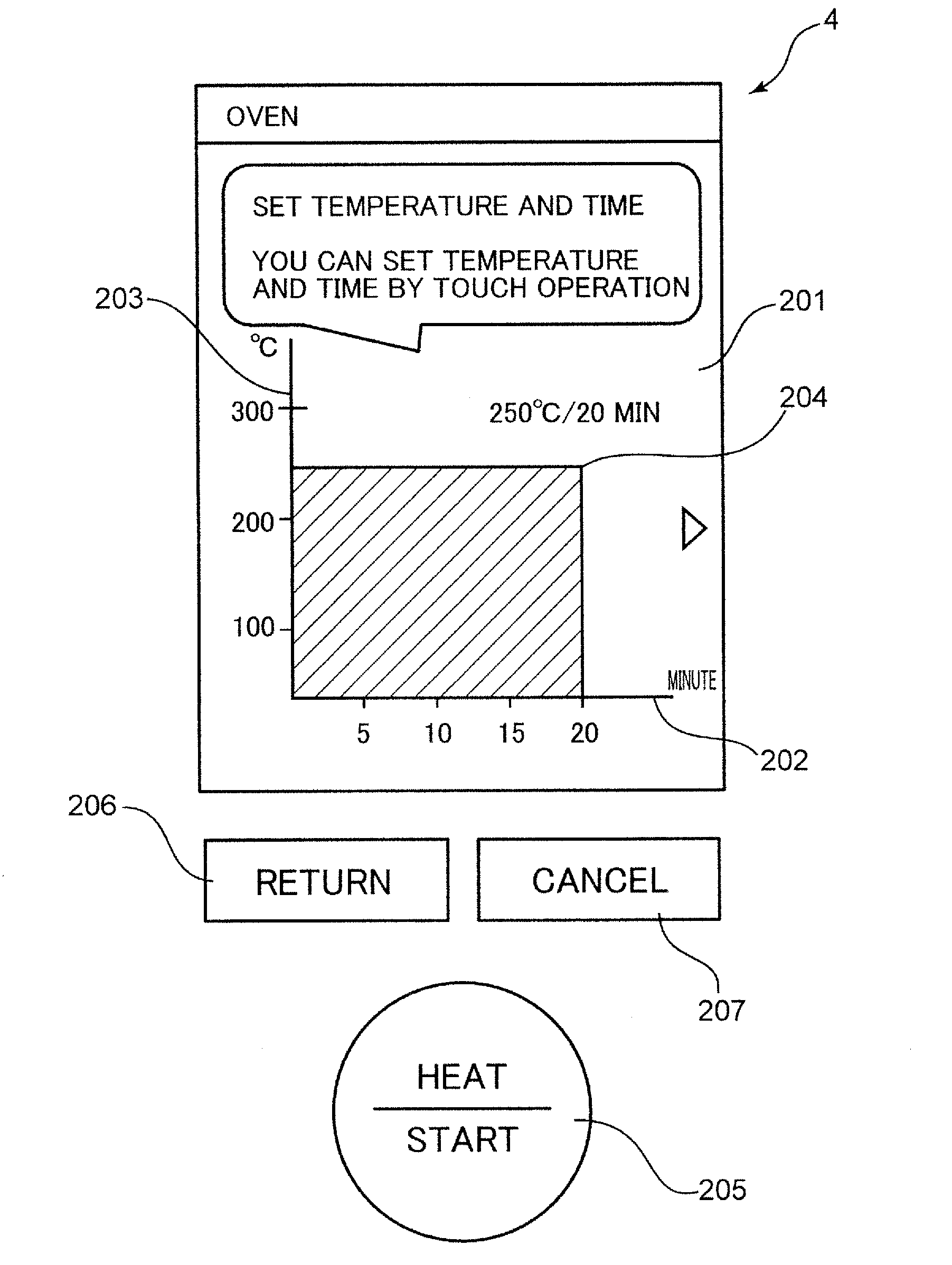
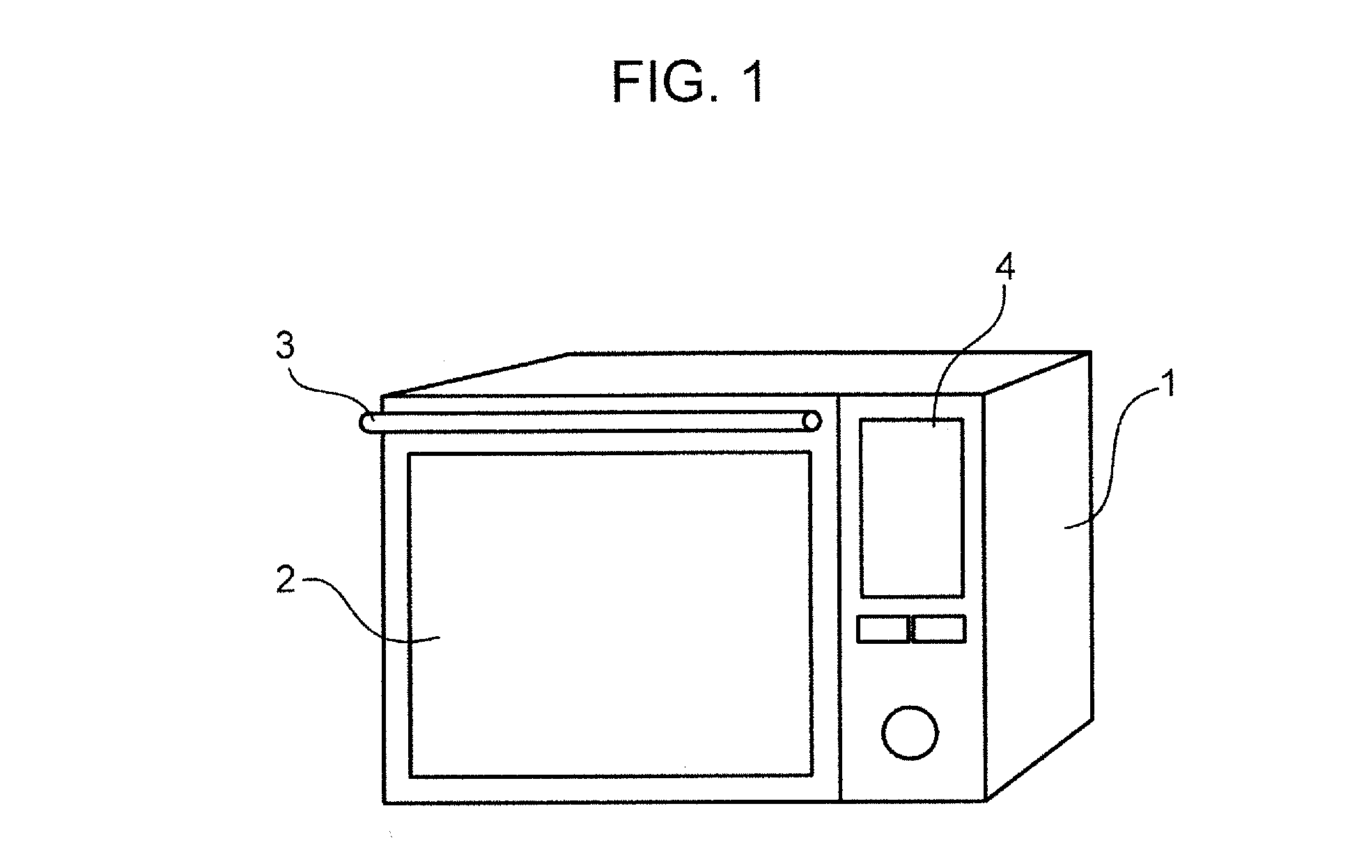
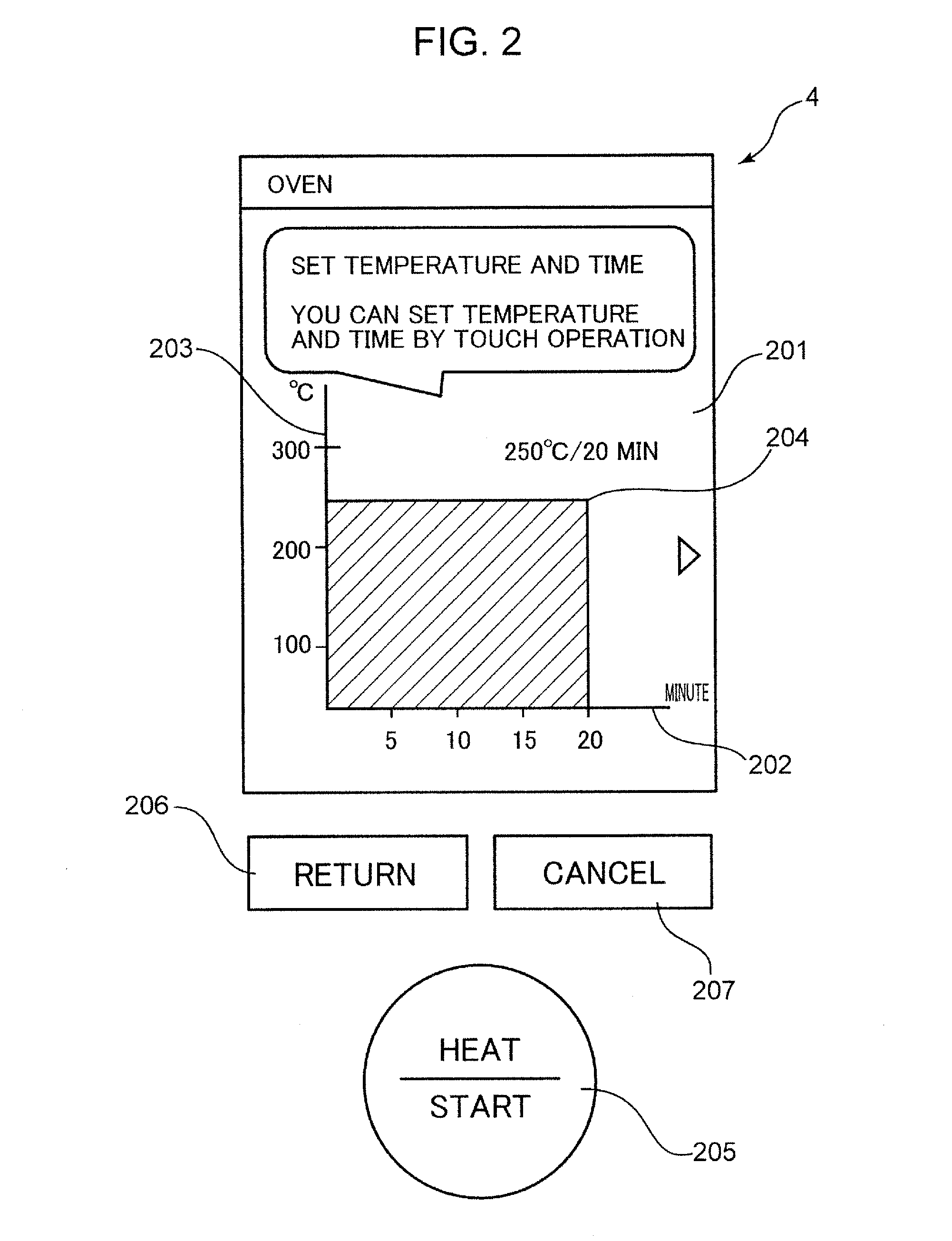
[0032]FIG. 1 is a diagram illustrating an external appearance of a microwave oven in the first embodiment of the invention. FIG. 2 is a diagram illustrating a configuration of an operation display unit of the microwave oven in the first embodiment of the invention. FIG. 3 is a block diagram illustrating a configuration of the operation display unit in the first embodiment of the invention. The configuration of the first embodiment is described using FIG. 1, FIG. 2, and FIG. 3. In the first embodiment, a microwave oven is described as an example of a household appliance provided with an operation device. The household appliance, however, is not limited to a microwave oven.

[0033]Referring to FIG. 1, the microwave oven is provided with a microwave oven housing 1, a door 2, a door handle 3, and an operation display unit 4. The microwave oven is an example of a cooking heater for heating food.

[0034]The microwave oven in the first embodiment is a microwave oven provided with a microwave c...

second embodiment

[0129]The external appearance of a microwave oven in the second embodiment is the same as the external appearance of the microwave oven in the first embodiment, and therefore, repeated description thereof is omitted herein.

[0130]FIG. 15 is a diagram illustrating a configuration of an operation display unit of the microwave oven in the second embodiment of the invention. FIG. 16 is a block diagram illustrating a configuration of the operation display unit in the second embodiment of the invention. The configuration of the second embodiment is described using FIG. 1, FIG. 15, and FIG. 16. In the second embodiment, a microwave oven is described as an example of a household appliance provided with an operation device. The household appliance, however, is not limited to a microwave oven.

[0131]Next, an external appearance configuration of an operation display unit 4 is described using FIG. 15. The operation display unit 4 illustrated in FIG. 15 is provided with a GUI operation display por...


PUM


Abstract

An operation device is provided with a GUI display unit which displays a power setting value for defining an operation power of a household appliance, and a time setting value for defining an operation time of the household appliance on an orthogonal coordinate system; and a touch operation unit which simultaneously accepts an input of the power setting value and an input of the time setting value to be displayed on the GUI display unit by an operation of letting a predetermined object touch the GUI display unit.

Description

TECHNICAL FIELD[0001]The present invention relates to an operation device and an operation method for operating a household appliance.BACKGROUND ART[0002]A conventional display device provided with a display unit including a touch panel is configured as follows. A plurality of images representing a plurality of alternatives are simultaneously displayed on a screen of the display unit. The user is allowed to successively touch a first image located at a first display position representing a first alternative, as one of the images, and a second image located at a second display position representing a second alternative, as the other one of the alternatives by the finger or by a pen-like object. When a changeover operation signal representing that the finger or the pen-like object successively touches the first image and the second image is received from the touch panel, the first image representing the first alternative and the second image representing the second alternative are cha...

Claims


Application Information

Patent Timeline
Patent Type & Authority Applications(United States)
IPC IPC(8): G06F3/0484F24C7/08H05B6/64G06F3/0488
CPCG06F3/04847H05B6/6435F24C7/086G06F3/04883
Inventor BAN, YASUHIROYAMASAKI, NAOKITOYOTA, HIROMI
Owner PANASONIC INTELLECTUAL PROPERTY MANAGEMENT CO LTD
Learn More