Larder systems having interlocking larder cases

a technology of locking larder and locking larder, which is applied in the direction of dismountable cabinets, cabinets, galleys, etc., can solve the problems of limitation restricting the removal and handling and affecting the service life of long larder cases

Active Publication Date: 2016-09-08
THE BOEING CO
View PDF8 Cites 4 Cited by
  • Summary
  • Abstract
  • Description
  • Claims
  • Application Information

AI Technical Summary

Benefits of technology

[0014]In some embodiments, the larder enclosure includes an enclosure latch detachably interlocked with the second latch, the first latch, or some other components of the first larder case. For example, the enclosure latch may detachably interlock the second side of the first larder case. This interlocking feature prevents the first larder case from sliding on the first bottom support, e.g., when the second larder case is not present and a space exists between the first larder case and the back wall of the larder enclosure. Specifically, the enclosure latch may prevent the first larder case from sliding on the first bottom support toward the back wall of the larder enclosure. In the same or another example, the enclosure latch may prevent the first larder case from sliding on the first bottom support away from the back wall of the larder enclosure. Specifically, the enclosure latch may prevent the first larder case from accidently going through the opening of the larder enclosure when the enclosure latch is engaged.
[0015]The enclosure latch may be disposed at the front wall of the larder enclosure, such as near the opening. It should be noted that when the first larder case is removed from the larder enclosure, the enclosure latch may detachably interlock with the second latch or some other component (e.g., the second side) of the second larder case thereby preventing the second larder case from sliding on the first bottom support. In this later case, the second larder case may be positioned away from the back wall of the larder enclosure such that there is an empty space between the back wall of the larder enclosure and the second larder case sufficient to fit another larder case. Specifically, the enclosure latch may prevent the second larder case from sliding on the bottom support toward the back wall of the larder enclosure. In the same or another example, the enclosure latch may prevent the second larder case from sliding on the first bottom support away from the back wall of the larder enclosure.

Problems solved by technology

Accessing and handling these long larder cases can be difficult especially when these cases positioned at low levels (e.g., near the floor).
Likewise, accessing large cases may be difficult at the high levels.
The space limitation restricts removal and handling of long larder cases.
Often, very little or even no space is available in a galley to position a long case for its loading and unloaded after the case is removed from its compartment.
Furthermore, long larder cases tend to be quite heavy when filled with various items.
Finally, using different length larder cases (e.g., shorter cases for overhead enclosures and longer cases for lower enclosures) provides better space utilization but, at the same time, makes handling these different cases difficult.
However, this stacking presents various other challenges.
One particular challenge is reaching and retrieving inner larder cases from a deep compartment when outer cases have been removed.
This operation may be particular difficult for compartments positioned at high and low levels.
Furthermore, if a compartment is only partially filled, the one or more remaining larder cases in the compartment may bounce between front and back walls of the larder enclosure.
This free movement in partially filled compartments may be highly undesirable in moving vehicles, such as aircraft.
For example, the weight of second latch 208b alone may not be sufficient to maintain this interlocking connection in vibrating or otherwise dynamic environments.

Method used


Image

  • Larder systems having interlocking larder cases
  • Larder systems having interlocking larder cases
  • Larder systems having interlocking larder cases

Examples


Embodiment Construction

[0036]In the following description, numerous specific details are set forth in order to provide a thorough understanding of the presented concepts. The presented concepts may be practiced without some or all of these specific details. In other instances, well known process operations have not been described in detail so as to not unnecessarily obscure the described concepts. While some concepts will be described in conjunction with the specific examples, it will be understood that these examples are not intended to be limiting.

[0037]Reference herein to “one example” or “one aspect” means that one or more feature, structure, or characteristic described in connection with the example or aspect is included in at least one implementation. The phrase “one example” or “one aspect” in various places in the specification may or may not be referring to the same example or aspect.

INTRODUCTION

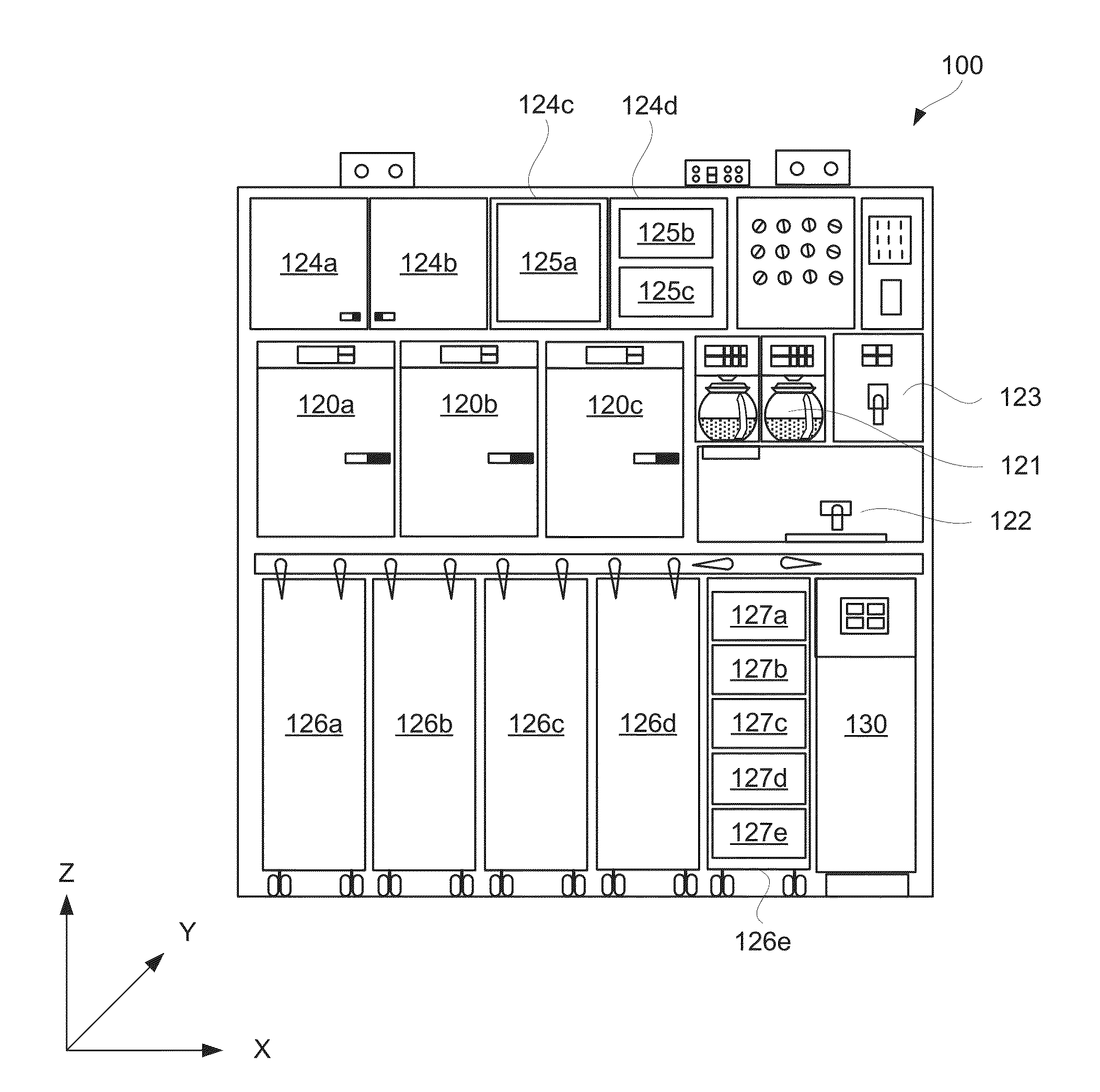
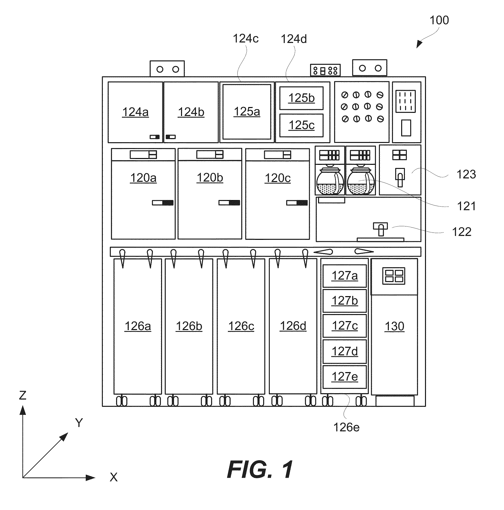
[0038]Many conventional larder systems have deep larder enclosures and use long larder cases to achiev...


PUM

PropertyMeasurementUnit
compressibleaaaaaaaaaa
structureaaaaaaaaaa
lengthaaaaaaaaaa

Abstract

Provided are larders systems, aircraft equipped with such systems, and methods of operating such systems. A larder system includes at least two larder cases removably disposed in the same compartment of a larder enclosure. The two cases are detachably interlocked with each other such that removal of the outer case from the enclosure advances the inner case closer to the opening. After the removal of the outer case, the inner case may be retained at the opening. The two cases may be interlocked when pushed against each other, such as when the outer case is inserted into the compartment containing the inner case. In some embodiments, a larder case may be interlocked with the larder enclosure or one of its components, such as a door. This enclosure interlocking allows for the larder case to retain its interlocked position when, for example, the enclosure is only partially filed.

Description

TECHNICAL FIELD[0001]This disclosure generally relates to larder systems used in galleys of aircraft and other types of vehicles. More specifically, this disclosure relates to larder systems, each having two or more detachably interlocked larder cases, which are removably disposed in the same compartment of a larder enclosure.BACKGROUND[0002]Aircraft and other types of vehicles, such as ships, trains, recreational vehicles (RVs), typically include service galleys for preparing meals and refreshments for passengers and crew. For example, a passenger aircraft may include one or more service galleys in a fuselage, such two service galleys positioned at each end of a fuselage. These service galleys or, simply, galleys may be used to store food, equipment, and other items used during operation of the aircraft. Various types of storage systems or, more specifically, larder systems are used for these purposes. Due to the space constraints and the need to store many different items, convent...

Claims


Application Information

Patent Timeline
Patent Type & Authority Applications(United States)
IPC IPC(8): B64D11/04A47B87/02A47B69/00A47B46/00A47B47/00
CPCB64D11/04A47B46/00A47B87/02A47B69/00A47B47/0091
Inventor VANDEWALL, CYNTHIA A.TAN, MING KWAN ESMONDCHEAH, KAI SHEN ELSTONBARY, HISHAM TAREK
Owner THE BOEING CO
Why Eureka
Try Eureka