Method and apparatus for attenuation correction of emission tomography scan data

a technology of emission tomography and attenuation correction, which is applied in the direction of instruments, magnetic measurements, and measurements using nmr, can solve the problems of inability to determine the suitable attenuation value of these signal changes, the inability to detect the signal cancellation in the magnetic resonance scan data, and the increase in susceptibility artifacts, etc., to achieve the effect of reducing artifacts, reducing the number of errors, and improving the resolution

Active Publication Date: 2016-09-08
SIEMENS HEALTHCARE GMBH
View PDF7 Cites 6 Cited by
  • Summary
  • Abstract
  • Description
  • Claims
  • Application Information

AI Technical Summary

Benefits of technology

[0032]In another embodiment, first magnetic resonance scan data are acquired using a first magnetic resonance sequence and second magnetic resonance scan data are acquired using a second magnetic resonance sequence, and the attenuation map is generated using the first magnetic resonance scan data and the second magnetic resonance scan data. It is particularly advantageous in this connection for the generation of the attenuation map to be a generation of a provisional attenuation map using the first magnetic resonance scan data, and an adjustment of the provisional attenuation map using the second magnetic resonance scan data. The first magnetic resonance scan data and the second magnetic resonance scan data can alternatively be incorporated together in the generation of the attenuation map. The image contents of the first magnetic resonance scan data therefore can be combined with image contents of the second magnetic resonance scan data, with the combined image contents then being incorporated in the generation of the attenuation map. In general it is advantageous for the second magnetic resonance scan data to represent information about the interference object and/or a tissue, which surrounds the interference object, which is complementary and/or supplementary to the first magnetic resonance scan data. For this purpose, for example, the second magnetic resonance scan data can have a higher resolution than the first magnetic resonance scan data, as described in the following. The second magnetic resonance scan data can purposefully map the interference object. Alternatively, the first magnetic resonance scan data can cover a greater body region than the second magnetic resonance scan data and therefore represent information about an attenuation of the emission tomography scan data from the larger body region. In particular, the first magnetic resonance sequence is designed differently from the second magnetic resonance sequence, for example, with respect to the type of magnetic resonance sequence and/or with respect to sequence parameters therefore used. A magnetic resonance sequence of the type that is conventionally used to create the attenuation map can be executed to acquire the first magnetic resonance scan data. A magnetic resonance sequence that has been specifically optimized for imaging in the vicinity of the interference object is advantageously used to acquire the second magnetic resonance scan data. The first magnetic resonance scan data and the second magnetic resonance scan data are acquired separately from each other in two mutually disjunct recording processes. The second magnetic resonance scan data can supply additional information that goes beyond the first magnetic resonance scan data, so that the attenuation map adjusted by the second magnetic resonance scan data has more accurate information with respect to attenuation in a spatial environment of the interference object than the provisional attenuation map. For example, the adjusted attenuation map can have fewer signal changes than the provisional attenuation map. In this way attenuation correction of the emission tomography scan data can be made using the attenuation map adjusted in this way.
[0033]In another embodiment, the first magnetic resonance sequence and the second magnetic resonance sequence have sequence parameters such that a resolution of the second magnetic resonance scan data is finer in at least one direction than a resolution of the first magnetic resonance scan data. In this way, the spatial environment of the interference object can be mapped in the second magnetic resonance scan data with a finer resolution than in the first magnetic resonance scan data. The resolution of the second magnetic resonance scan data being finer than the resolution of the first magnetic resonance scan data means that the resolution of the second magnetic resonance scan data is higher than the resolution of the first magnetic resonance scan data, or that at least one edge length of voxels of the second magnetic resonance scan data is shorter than the corresponding edge length of voxels of the first magnetic resonance scan data. As described immediately below, an examination region of the second magnetic resonance scan data, which is mapped with a finer resolution, is smaller than an examination region of the first magnetic resonance scan data. By using the finer resolution, the second magnetic resonance scan data can map the region around the interference object in order to generate the attenuation map. For example, a reduction in artifacts in the second magnetic resonance scan data, in particular specifically for a spatial environment of the interference object, can be attained in this way compared to the first magnetic resonance scan data.
[0034]In another embodiment, the first magnetic resonance sequence has a first recording volume and the second magnetic resonance sequence a second recording volume, wherein the second record...

Problems solved by technology

In magnetic resonance imaging, there is often an interference object in the examination object which disturbs the magnetic resonance imaging at least locally.
The magnetic interference field can lead to susceptibility artifacts that typically increase with the strength of the basic magnetic field of the magnetic resonance device.
This interference field, in particular the susceptib...

Method used


Image

  • Method and apparatus for attenuation correction of emission tomography scan data
  • Method and apparatus for attenuation correction of emission tomography scan data
  • Method and apparatus for attenuation correction of emission tomography scan data

Examples


first embodiment

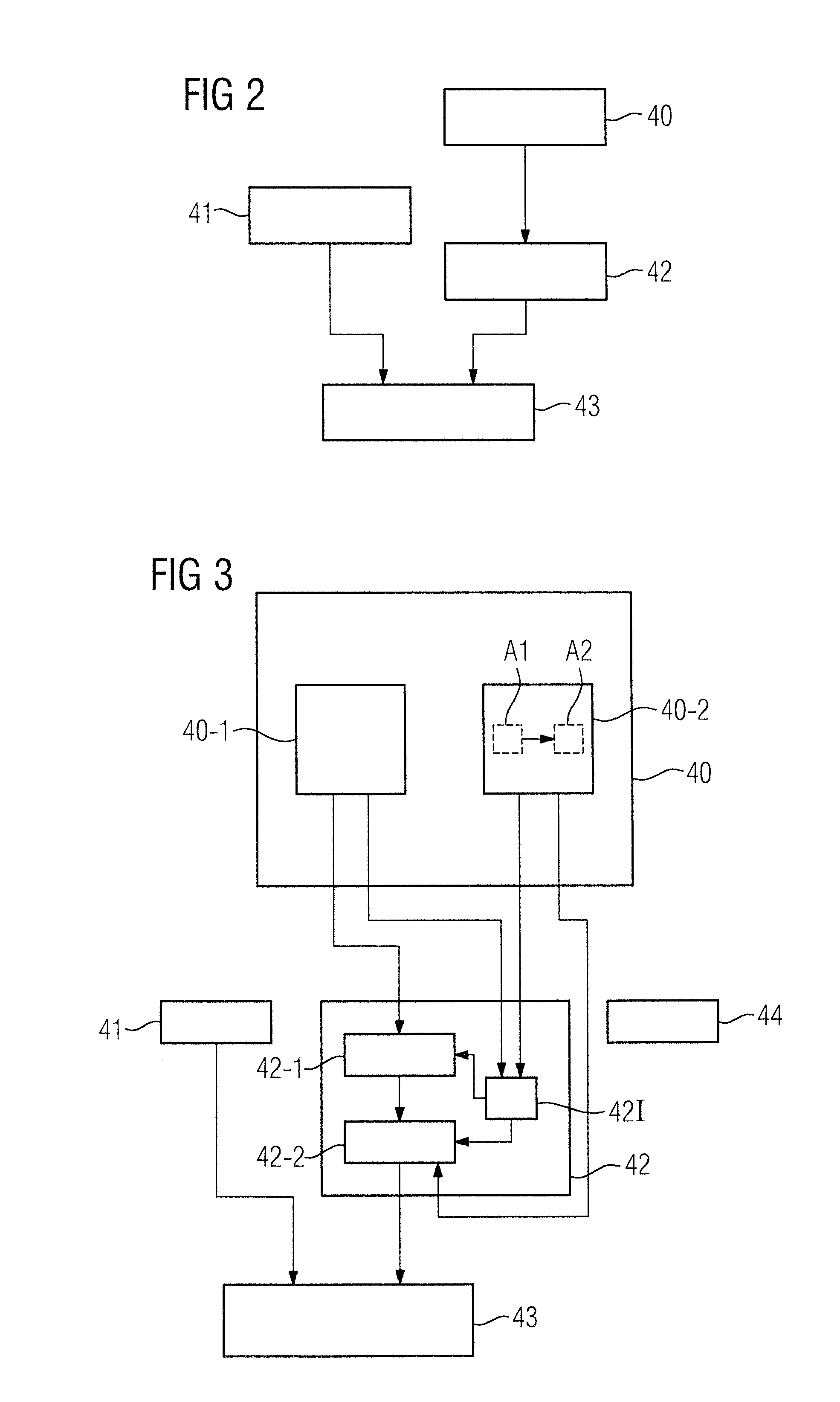
[0067]FIG. 2 shows a flowchart of an inventive method for attenuation correction of emission tomography scan data.

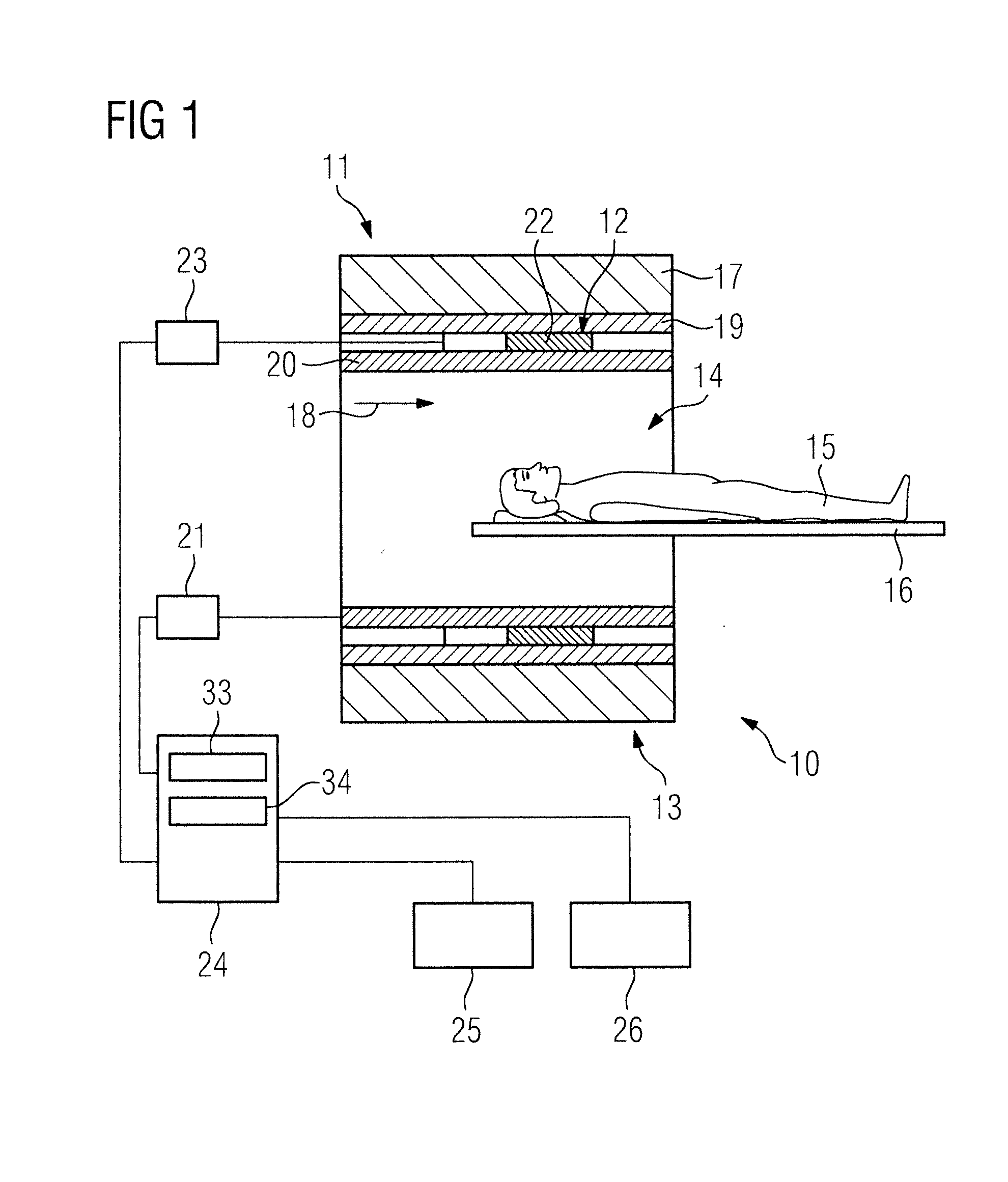
[0068]In a first method step 40 magnetic resonance scan data of the examination object are acquired by means of the magnetic resonance scan data acquisition scanner 11, wherein a magnetic resonance sequence, which is designed to at least partially compensate interference due to the magnetic interference field, is used to acquire the magnetic resonance scan data. The magnetic resonance sequence defines a sequence of control commands with which the magnetic resonance scan data acquisition scanner 11 acquires the magnetic resonance scan data.

[0069]In a further method step 41, emission tomography scan data of the examination object are acquired by means of the emission tomography scan data acquisition scanner 12. A simultaneous magnetic resonance emission tomography examination of the examination object 15 can be implemented by the magnetic resonance emission tomography appa...

second embodiment

[0072]FIG. 3 shows a flowchart of an inventive method for attenuation correction of emission tomography scan data.

[0073]The following description is essentially limited to the differences from the exemplary embodiment in FIG. 2, with reference being made in respect of unchanging method steps to the description of the exemplary embodiment in FIG. 2. Method steps that are essentially unchanging are basically numbered with the same reference characters.

[0074]The second embodiment of the inventive method shown in FIG. 3 includes method steps 40, 41, 42, 43 of the first embodiment of the inventive method according to FIG. 2. In addition, the second embodiment of the inventive method shown in FIG. 3 has additional method steps and substeps. A method sequence alternative to FIG. 3, which has only some of the additional method steps and / or substeps in FIG. 2, is also conceivable. Of course a method sequence alternative to FIG. 3 can also have additional method steps and / or substeps.

[0075]In...


PUM


Abstract

In a method for attenuation correction of emission tomography scan data acquired from an examination object in a combined magnetic resonance emission tomography apparatus, wherein an interference object is situated in the examination region, which causes a magnetic interference field during combined magnetic resonance emission tomography imaging, magnetic resonance scan data of the examination object are acquired by executing a magnetic resonance sequence designed to at least partially compensate inference due to the magnetic interference field. Emission tomography scan data are acquired and an attenuation map is generated using the acquired magnetic resonance scan data. Attenuation correction of the emission tomography scan data is implemented using the generated attenuation map.

Description

BACKGROUND OF THE INVENTION[0001]1. Field of the Invention[0002]The invention concerns a method for attenuation correction of emission tomography scan data, as well as a combined magnetic resonance emission tomography apparatus and a non-transitory, computer-readable data storage medium encoded with programming instructions, for implementing such a method.[0003]2. Description of the Prior Art[0004]In the scanner of a magnetic resonance apparatus, also called a magnetic resonance tomography system, the body of an examination person, in particular a patient, to be examined is conventionally exposed by a basic field magnet to a relatively high basic magnetic field, for example of 1.5 or 3 or 7 tesla. In addition, gradient switching operations occur with the use of a gradient coil unit. Radio-frequency pulses, for example excitation pulses, are then emitted by a radio-frequency antenna unit by suitable antenna devices, and this leads to the nuclear spins of specific atoms, which are exc...

Claims


Application Information

Patent Timeline
IPC IPC(8): G01R33/565G01R33/48
CPCG01R33/481G01R33/56563G01T1/1603
Inventor BACHSCHMIDT, THERESAFENCHEL, MATTHIASJAKOBY, BJOERNNITTKA, MATHIAS
Owner SIEMENS HEALTHCARE GMBH
Why Eureka
Try Eureka