Consensus-based power control apparatus

Active Publication Date: 2016-09-08
NATIONAL TSING HUA UNIVERSITY
View PDF3 Cites 15 Cited by
  • Summary
  • Abstract
  • Description
  • Claims
  • Application Information

AI Technical Summary

Benefits of technology

[0023]Further, when a plurality of power control apparatuses of the present invention are applied in a grid system having a plurality of power generating apparatuses, the power control apparatuses are capable of distributing real power and reactive power input signals of the power generating apparatuses so as to cause the real power and reactive power input signals of the power generating apparatuses to become (

Problems solved by technology

However, when a plurality of synchronous generators 1 are applied in a grid system, since the grid system lacks the ability to distribute real power input signals Pe and reactive power input signals (not shown) of the synchronous generators 1

Method used


Image

  • Consensus-based power control apparatus
  • Consensus-based power control apparatus
  • Consensus-based power control apparatus

Examples


Example

[0033]The following illustrative embodiments are provided to illustrate the disclosure of the present invention, these and other advantages and effects can be apparent to those in the art after reading this specification.

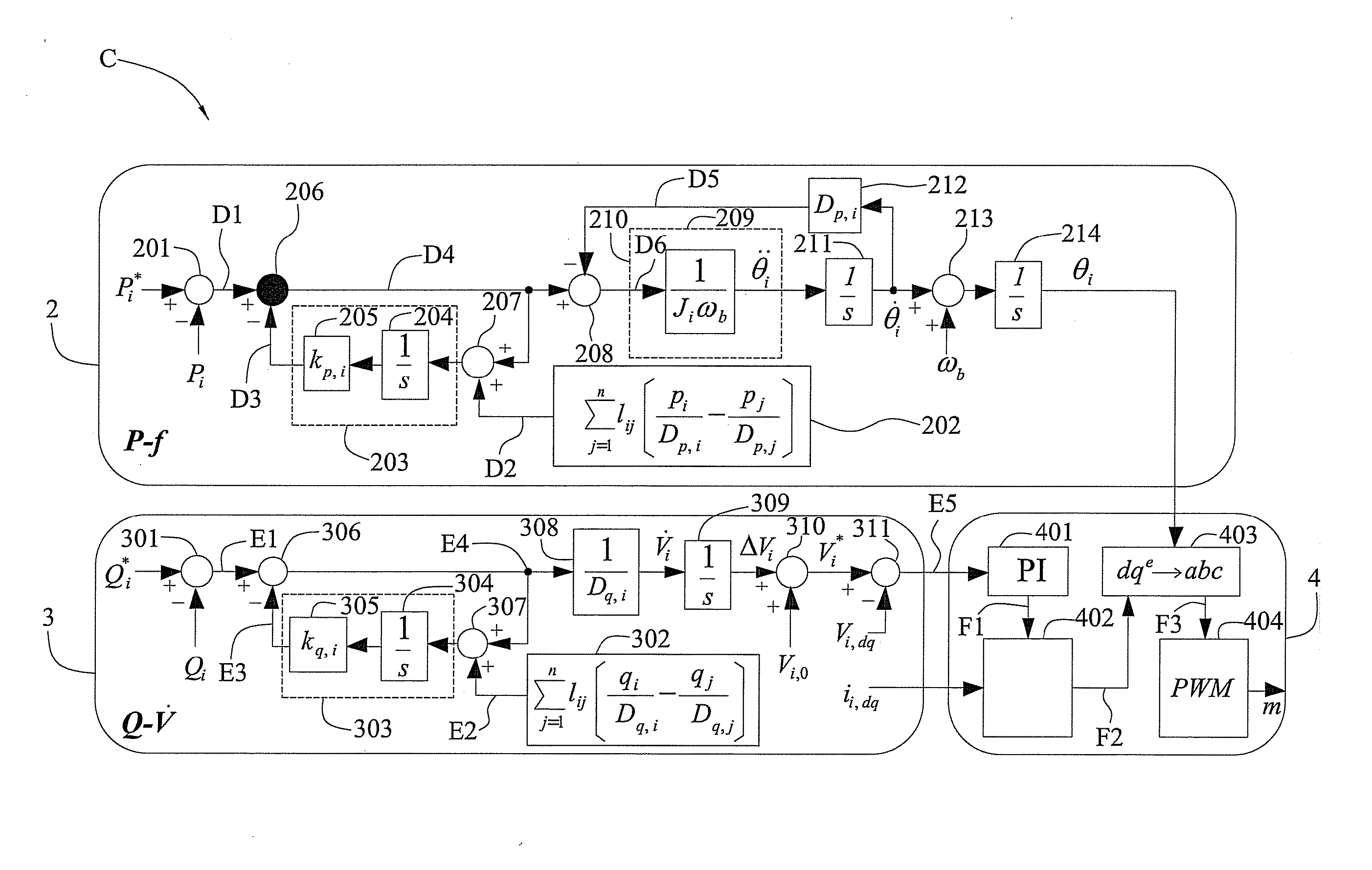
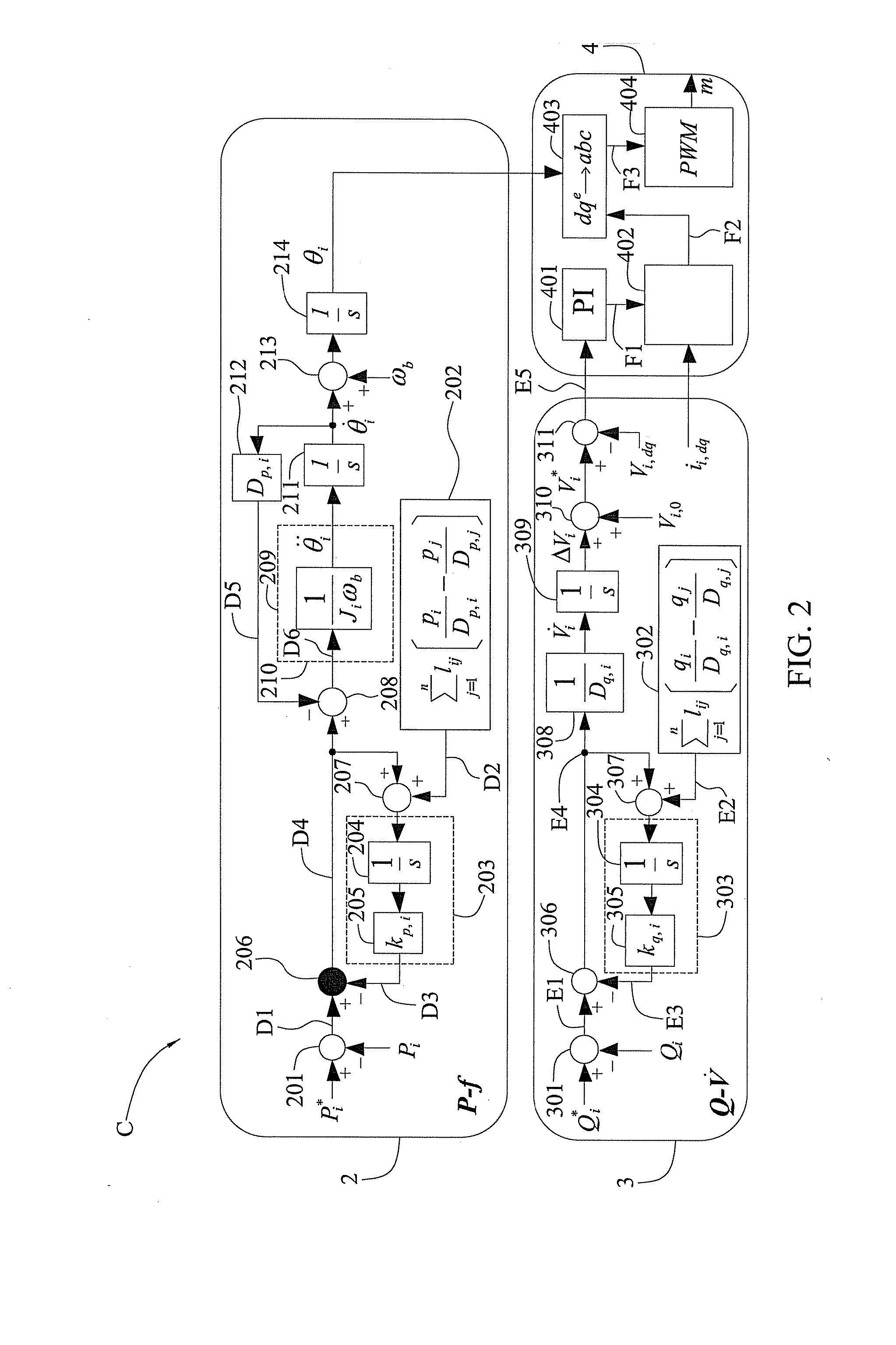
[0034]FIG. 2 is a schematic block diagram of a consensus-based power control apparatus C of the present invention, and FIG. 3 is a schematic block diagram showing application or mounting of a plurality of power control apparatuses C (for example, six power control apparatuses C3, C4, C5, C7, C10 and C13) of the present invention in a plurality of power generating apparatuses G (for example, six power generating apparatuses G3, G4, G5, G7, G10 and G13) of a grid system 5, respectively.

[0035]In the present embodiment, the grid system 5 of FIG. 3 has a plurality of buses B (for example, fourteen buses B1 to B14) and a plurality of transmission lines l for electrically connecting the power generating apparatuses G, the power control apparatuses C and a plurality of load...


PUM


Abstract

A consensus-based power control apparatus is provided, which includes a real power control module and a reactive power control module. A real power consensus signal between a first power generating apparatus and a second power generating apparatus is provided and a frequency restoration signal is generated according to the real power consensus signal, thereby allowing the real power control module to generate a real power output signal. A reactive power consensus signal between the first power generating apparatus and the second power generating apparatus is provided and a voltage differential restoration signal is generated according to the reactive power consensus signal, thereby allowing the reactive power control module to generate a reactive power output signal. Therefore, the invention can control real power and reactive power input signals (i.e., actual real power and reactive power outputs) of the first power generating apparatus in a grid system.

Description

BACKGROUND OF THE INVENTION[0001]1. Field of the Invention[0002]The present invention relates to power control apparatuses, and more particularly, to a consensus-based power control apparatus applicable to a grid system having at least two power generating apparatuses.[0003]2. Description of Related Art[0004]In a grid system constituted by a plurality of power generating apparatuses such as synchronous generators, wind power generators and water power generators, since the power generating apparatuses usually generate significantly different real power input signals (representing actual real power outputs of the apparatuses) or reactive power input signals (representing actual reactive power outputs of the apparatuses) and the grid system lacks an ability to distribute the real power input signals and the reactive power input signals of the power generating apparatuses, the real power input signals and the reactive power input signals of the power generating apparatuses cannot becom...

Claims


Application Information

Patent Timeline
IPC IPC(8): G06F1/32
CPCG06F1/3296G06F1/3287H02J3/38H02J3/48H02J3/50
Inventor CHU, CHIA-CHILU, LIN-YU
Owner NATIONAL TSING HUA UNIVERSITY
Why Eureka
Try Eureka