Optical head and optical information device
a head and optical technology, applied in the field of optical information processors, can solve the problems of difficult to make the working distance of an objective lens, and achieve the effects of good stability, low jitter, and high snr
- Summary
- Abstract
- Description
- Claims
- Application Information
AI Technical Summary
Benefits of technology
Problems solved by technology
Method used
Image
Examples
embodiment 1
[0083]Hereinafter, a Preferred Embodiment of an Optical head according to the present invention will be described.
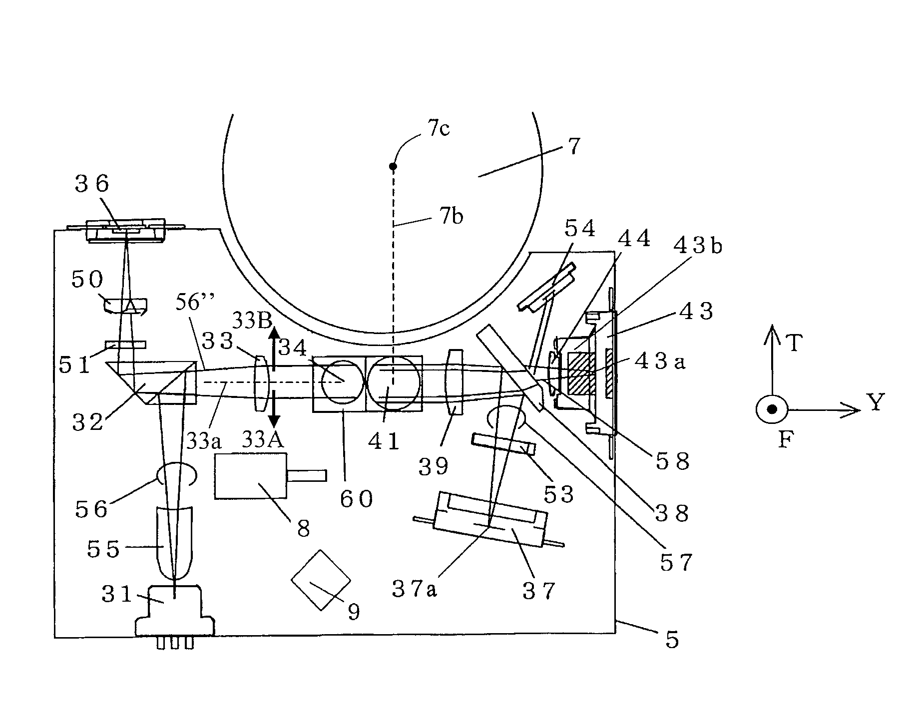
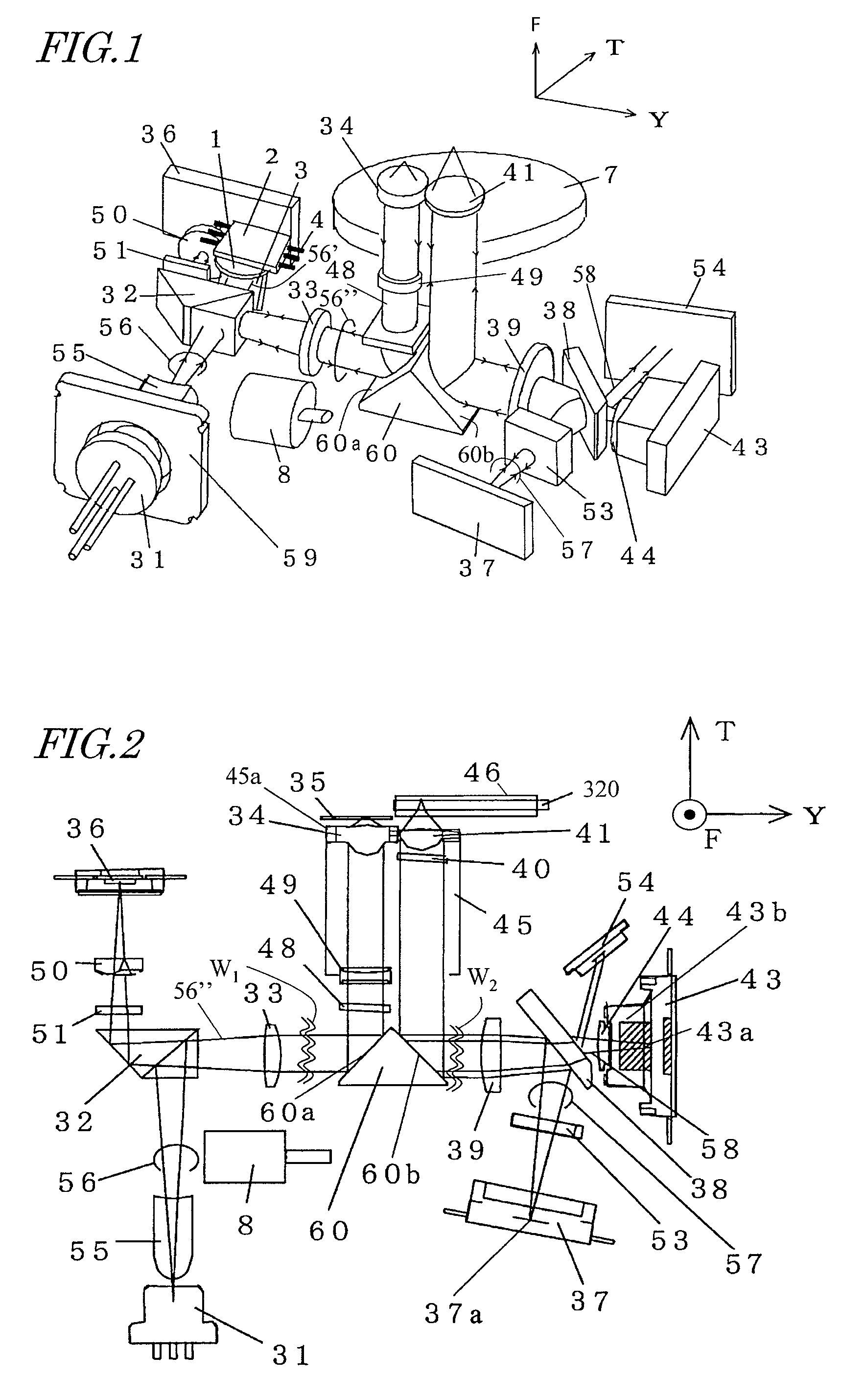
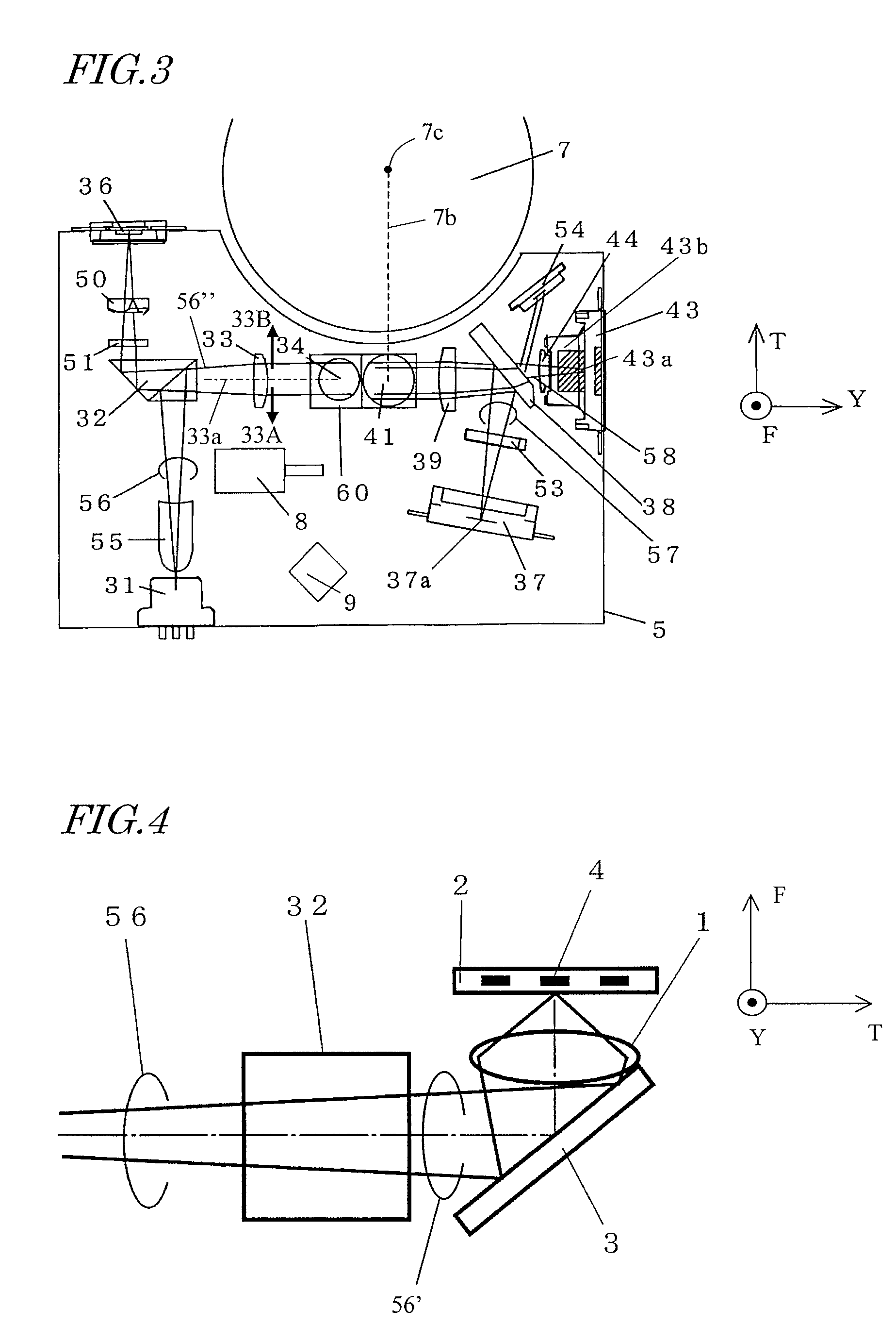
[0084]FIG. 1 is a perspective view illustrating mainly the arrangement of an optical system in an optical head according to the present invention. FIG. 2 schematically illustrates some of the members shown in FIG. 1 as a combination of a plan view and a side view. And FIG. 3 is a plan view of the optical head shown in FIG. 1. In these drawings, the reference sign T denotes a tracking direction, F denotes a focusing direction, and Y denotes a direction perpendicular to the tracking direction. In other words, Y is the direction in which a series of pits or track grooves run.
[0085]In FIG. 2, the portion of the optical head between the two wave lines W1 and W2 is a side view, which is viewed on a plane parallel to the one defined by the directions F and Y. On the other hand, the other portions of the optical head outside of the two wave lines W1 and W2 are a plan view, which...
embodiment 2
[0147]A preferred embodiment of an optical information processor according to the present invention will be described with reference to FIG. 7.
[0148]This optical information processor 104 includes an optical head 402, an electrical circuit 403, and a motor 404.
[0149]The optical disks 407, 408 and 409 have mutually different storage densities. One of these optical disks 407 to 409 is supposed to be picked by the operator and put on a turntable 405. The optical disk mounted is fixed by a clamper 406 onto the turntable 405 and then rotated and driven by the motor 404. The optical disks 407 to 409 correspond to the first, second and third optical disks 35, 320 and 46 of the first preferred embodiment described above.
[0150]The optical head of the first preferred embodiment described above can be used effectively as the optical head 402. The optical head can be moved in the tracking direction by a drive mechanism 401 such as a traverse motor and can jump to a target track.
[0151]Based on t...
embodiment 3
[0153]A preferred embodiment of a computer according to the present invention will be described with reference to FIG. 8.
[0154]This computer 105 includes an optical information processor 501, which corresponds to the optical information processor 104 that has just been described as the second preferred embodiment of the present invention. The computer 105 further includes an input device 503 such as a keyboard, a mouse or a touchscreen panel for entering information and an arithmetic-logic unit 502 such as a central processing unit (CPU) for performing arithmetic and logic operations based on the information entered through the input device 503 or the information read by the optical information processor 501.
[0155]The computer 105 further includes an output device 504 such as a CRT, an LCD or a printer for displaying information such as the results of the computations done by the arithmetic-logic unit 502.
[0156]The computer 105 includes the optical information processor 501 that cor...
PUM
| Property | Measurement | Unit |
|---|---|---|
| width | aaaaa | aaaaa |
| width | aaaaa | aaaaa |
| wavelength | aaaaa | aaaaa |
Abstract
Description
Claims
Application Information
 - R&D
- Intellectual Property
- Life Sciences
- Materials
- Tech Scout
- Unparalleled Data Quality
- Higher Quality Content
- 60% Fewer Hallucinations
Browse by: Latest US Patents, China's latest patents, Technical Efficacy Thesaurus, Application Domain, Technology Topic, Popular Technical Reports.
© 2025 PatSnap. All rights reserved.Legal|Privacy policy|Modern Slavery Act Transparency Statement|Sitemap|About US| Contact US: help@patsnap.com


