
Passive Q-switch laser device

a laser device and q-switch technology, applied in the direction of laser details, active medium materials, electrical devices, etc., can solve the problems of promoting emission, and achieve the effect of high excitation efficiency and small delay time required for reaching the q-switch oscillation

Active Publication Date: 2018-02-06
INTER UNIV RES INST NAT INST OF NATURAL SCI
View PDF5 Cites 0 Cited by
  • Summary
  • Abstract
  • Description
  • Claims
  • Application Information

AI Technical Summary

Benefits of technology

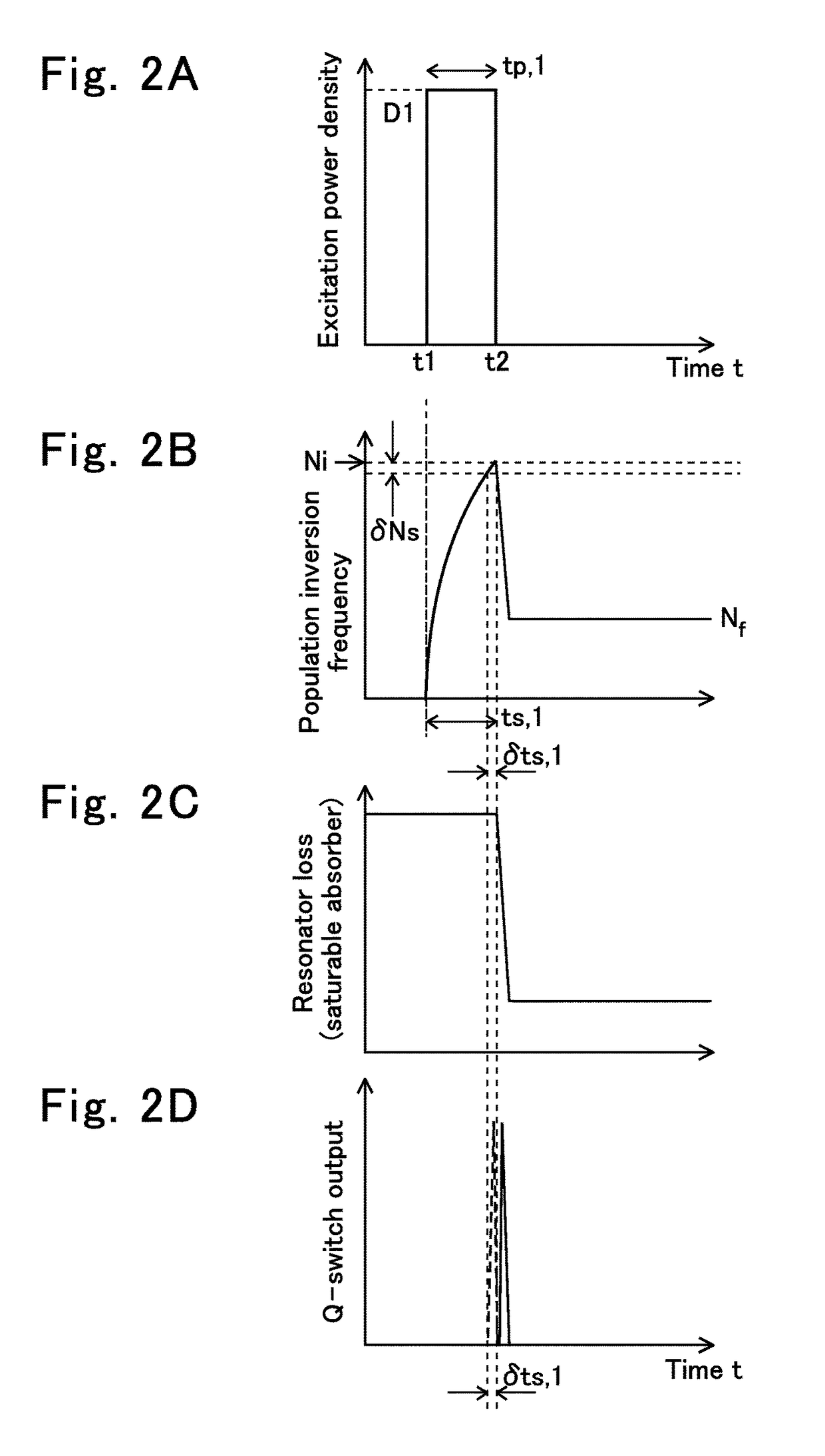
The invention is a device called a power density controller that ensures the power of the laser's excitation light is at least as strong as the power needed to achieve maximum oscillation. This ensures that the time needed to reach maximum oscillation after excitation is either the same or shorter than the time needed for the laser material to return to its original state. This results in higher efficiency and less delay time, which leads to improved performance and reduced jitter.

Problems solved by technology

However, the induced emission is promoted at once due to the excessively high gain.

Method used


Image

  • Passive Q-switch laser device
  • Passive Q-switch laser device
  • Passive Q-switch laser device

Examples


embodiment

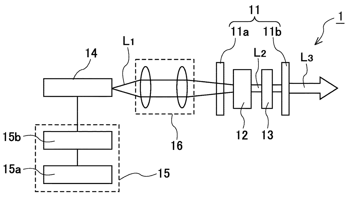
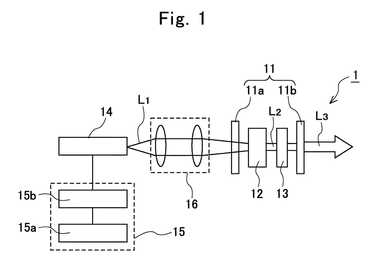
[0029]A passive Q-switch laser device 1 according to the embodiment of the present invention includes, as illustrated in FIG. 1, an input mirror element 11a and an output mirror element 11b forming a resonator 11; a laser gain medium 12 arranged inside the resonator 11; a saturable absorber 13 arranged inside the resonator 11; an excitation light source 14 that excites the laser gain medium 12; and a power density controller 15 that makes power density of excitation light from the excitation light source 14 equal to or greater than power density so that delay time required for reaching oscillation after start of the excitation of the laser gain medium 12, that is, oscillation start time (ts) becomes equal to or shorter than a laser upper energy level lifetime of the laser gain medium 12.

[0030]The input mirror element 11a is formed by, for example, evaporating a dielectric multilayer film to a quartz glass or BK7 plate, and transmits excitation light L1 from the excitation light sour...


PUM


Abstract

Provided is a passive Q-switch laser device possessing a power density controller (15) making power density of excitation light from an excitation light source (14) equal to or greater than power density so that delay time required for reaching oscillation after start of excitation of a laser gain medium (12) becomes equal to or shorter than a laser upper energy level lifetime of the laser gain medium (12).

Description

TECHNICAL FIELD[0001]The present invention relates to a passive Q-switch laser device that would generate laser light with a high power and a short pulse by using a Q-switching technology.BACKGROUND ART[0002]Further research and developments of laser devices directed to achieve a higher power, a shorter pulse, and a shorter wavelength of output light have been made. Among the aforementioned devices, a Q-switch laser device using a Q-switching technology has received a lot of attention from where output pulse laser light with a high power and a short pulse could be obtained. In the Q-switching technology, with a configuration including not only a gain medium but also a Q-switch element in a resonator, the laser oscillation is controlled by a varied Q-value of the resonator determined by the Q-switch element laser oscillation, thereby the output laser light with a short pulse and a high power could be provided.[0003]Various kinds of Q-switching technologies have been known. Among the ...

Claims


Application Information

Patent Timeline
Patent Type & Authority Patents(United States)
IPC IPC(8): H01S3/11H01S3/0941H01S3/16
CPCH01S3/1115H01S3/1643H01S3/1611H01S3/0941H01S3/094053H01S3/094076H01S3/09415H01S3/10053H01S3/1022H01S3/113
Inventor TAIRA, TAKUNORIKAUSAS, ARVYDASZHENG, LIHE
Owner INTER UNIV RES INST NAT INST OF NATURAL SCI
Learn More