Eureka AIR delivers breakthrough ideas for toughest innovation challenges, trusted by R&D personnel around the world.

Device and method for measuring the optical properties of an object

a technology of optical properties and devices, applied in the direction of optical radiation measurement, fluorescence/phosphorescence, luminescent dosimeters, etc., can solve the problems of parallel measurement, i.e. inability to simultaneously measure a plurality of measurement volumes in the object, and increase the transmission of illumination radiation

Inactive Publication Date: 2007-02-15
EVOTEC TECH GMBH
View PDF7 Cites 15 Cited by
  • Summary
  • Abstract
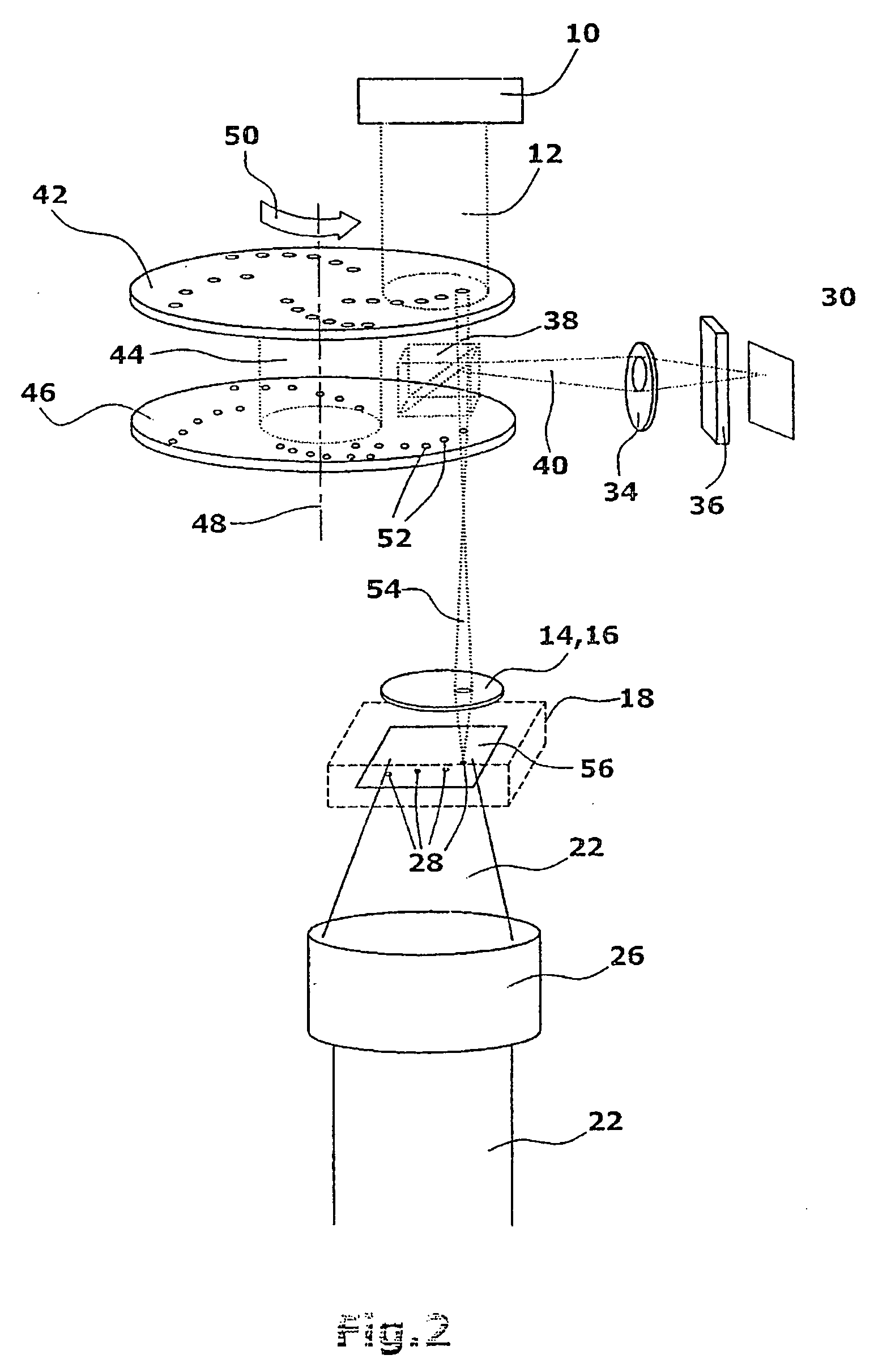
  • Description
  • Claims
  • Application Information

AI Technical Summary

Benefits of technology

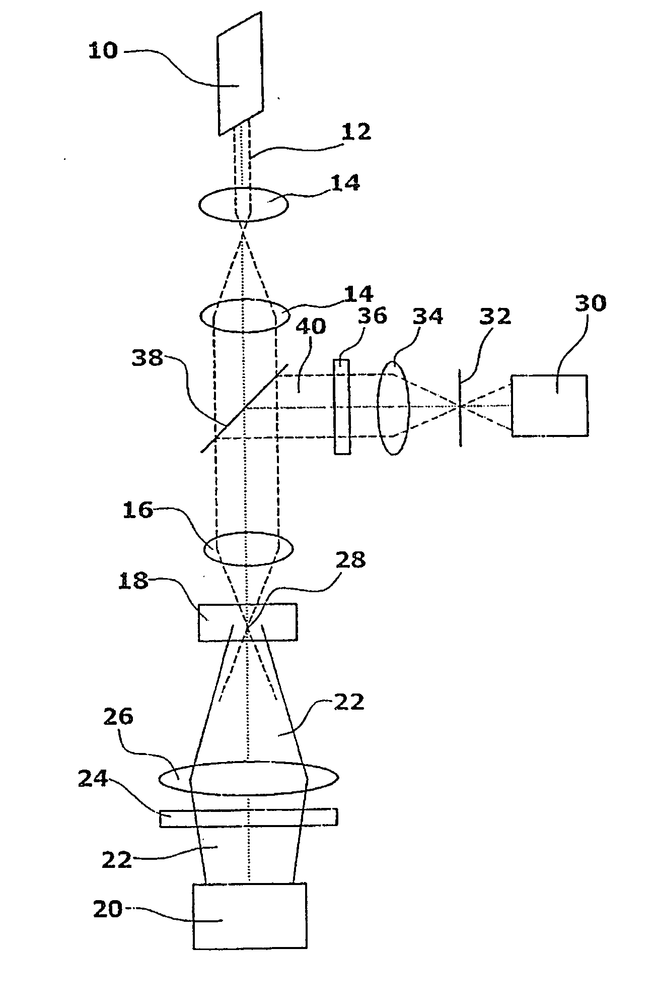
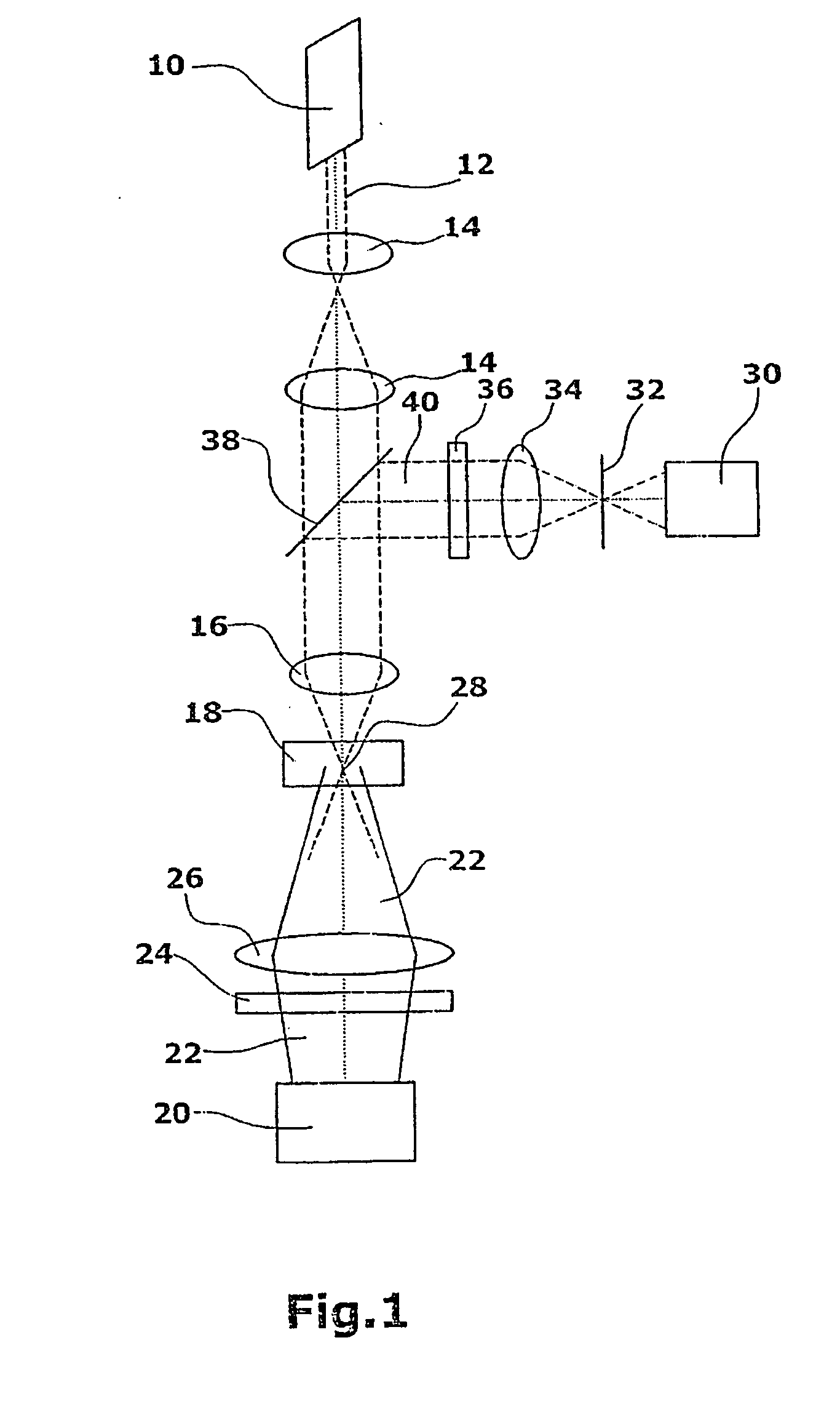
[0007] The inventive device for measuring optical properties of an object, particularly of a chemical and / or biological sample comprising particles such as cells and the like, is suited particularly for measuring the optical transmission and absorption properties of the object. The device comprises an illumination light source for illumination of the object. The illumination light source is particularly a broad-band light source, e.g. a mercury or xenon lamp followed by a filter for selection of a spectral region. By way of alternative, use can be made of a laser source with suitable beam-widening optics. Further, the device comprises an excitation light source which is preferably a laser light source. The excitation light source is suited, by means of the radiation used, to change the optical characteristics of the object. In doing so, the excitation light source will particularly change the population density of the basic condition of the molecules under examination. Further, the device comprises a detection unit such as e.g. a CCD array, for detecting the radiation emitted by the object. The radiation in this case can be particularly the radiation of the illumination light source passing through the object so that a transmission light measurement will be performed. According to the invention, the illumination light source will illuminate a spatially dimensioned portion of the object. Thus, the illumination light source is not focused on the measurement volume or the individual measurement volumes within the object. The excitation light source, on the other hand, is focused onto at least one measurement volume and preferably a plurality of measurement volumes. Thus, the excitation light source will preferably illuminate a plurality of small measurement volumes at the same time. Here, the illumination of the individual measurement volumes is performed on the object plane imaged on the detector device. The portion of this object plane imaged onto the detector device is at least partially congruent with the object portion which is illuminated by the illumination light source. The provision of a spatially resolving detector such as e.g. a CCD array or also of individual detectors makes it possible to examine preferably the transmission through the individual measurement volumes. Thus, the device of the invention can be used to examine a plurality of individual measurement volumes of the sample in parallel.
[0008] For generating a plurality of measurement volumes in the object plane imaged on the detector device, an array of pinholes (apertures) arranged on a rotating so-called Nipkow disk can be imaged into the object. To increase the excitation efficiency, a microlens array can be provided within the excitation beam path upstream of the pinhole array for focusing the excitation radiation onto the individual pinholes.
[0019] According to a preferred embodiment of the method of the invention which is preferably performed by the above described device of the invention, it is provided that, in a first step, the illumination radiation transmitted through the object is measured at a first intensity of the excitation radiation. Through a second measurement, the transmitted illumination radiation is measured at a second intensity of the excitation radiation. Thereafter, a comparison is performed between the two measurement values, particularly between the intensity values of the illumination radiation transmitted through the corresponding measurement volumes. Alternatively, it can be provided that the intensity of the excitation radiation is modulated at a rate which is larger than the scanning rate of the scan process, and that the amplitude of the variations of the intensity transmitted through the object can be detected by the detector.
[0023] Further, the device of the invention makes it possible to measure local concentrations of absorbing molecules, particularly colorant molecules. As compared to the known measurement of the fluorescence intensity, the measurement of the absorption as proposed herein offers the advantage of being largely independent of the emission properties of the molecules, which properties are in practice often influenced or adulterated by the chemical environment of the molecules.
[0028] By the provision of illumination and / or excitation radiation which is e.g. pulsed or modulated in another manner, it is possible to achieve a temporal separation between effects caused by the illumination radiation and / or the excitation radiation. This can be carried out particularly with the aid of time-resolving detector devices.

Problems solved by technology

This will result in a seemingly increased transmission of the illumination radiation because of the occurrence of additional photons emitted in the object which have the same wavelength.
However, this arrangement suffers from the basic disadvantage that a parallelized measurement, i.e. a simultaneous measurement of a plurality of measurement volumes in the object, is not possible because the detector will always capture the light of all measurement volumes together and a spatial assignment will not be possible.

Method used


Image

  • Device and method for measuring the optical properties of an object
  • Device and method for measuring the optical properties of an object
  • Device and method for measuring the optical properties of an object

Examples


Embodiment Construction

[0034] The device comprises an excitation light source 10 whose excitation light beam is collimated by an optics device 14. By means of a further optics device 16, the excitation beam is focused within an object 18 which is particularly a chemical and / or optical sample which particularly comprises particles such as e.g. cells. The focus or the foci of the excitation radiation will determine the site of one or a plurality of measurement volumes 28 within the object.

[0035] For performing the measurement of optical properties of an object, particularly for performing transmission measurements, an illumination light source 20 is provided on the side of the object 18 opposite from the excitation light source. In the presently described embodiment, the illumination radiation issuing from illumination light source 20 has a different wavelength from that of the excitation light. The illumination beam 22 will pass through a color filter 24, if provided, and an optics device 26 which is pref...


PUM

PropertyMeasurementUnit
wavelengthaaaaaaaaaa
wavelength rangeaaaaaaaaaa

Abstract

A device for measuring the optical properties of an object, particularly of a chemical and / or biological sample, comprises an illumination light source for illuminating the object. Further, an excitation light source is provided for illuminating the object, wherein the radiation of the excitation light source being suited to change the optical properties of the object. Further, the excitation radiations is focused in a measurement volumes arranged within the object. By means of a detector device, there can be detected preferably the transmission of the illumination radiation through the object within the measurement volume.

Description

FIELD OF THE INVENTION [0001] The invention relates to a device and a method for measuring optical properties of an object, preferably for measuring the optical transmission or absorption properties of the object. Particularly, the object can be a chemical and / or biological sample which preferably comprises particles such as cells. DISCUSSION OF THE BACKGROUND ART [0002] For examining the transmission properties of objects, it is known to illuminate the sample both by an excitation light source, also referred to as a pump light source, and by an illumination light source, also referred to as a sample light source. The light can be visible light or non-visible light. In the process, the molecules of the object under examination are excited by the excitation light source so that the population density of the basic state of the molecule is reduced. By use of the illumination light source, the condition of the molecules can be analyzed in different manners. For instance, there is known ...

Claims


Application Information

Patent Timeline
Patent Type & Authority Applications(United States)
IPC IPC(8): G01N21/59G01N21/17G01N21/63G01N21/64G02B21/00
CPCG01N21/31G01N21/636G02B21/0076G01N2021/6463G02B21/0044G01N21/645
Inventor MULLER, JURGENGORBOW, NORBERT
Owner EVOTEC TECH GMBH
Why Eureka
Eureka Blog
Learn More