A heat dissipating enclosure with integrated cooling fins

Inactive Publication Date: 2016-09-15
MARCHESI METAL TECH SUZHOU
View PDF10 Cites 2 Cited by
  • Summary
  • Abstract
  • Description
  • Claims
  • Application Information

AI Technical Summary

Benefits of technology

[0005]The objection of the invention is to provide a heat dissipation housing structure connected to heat dissipation fins accommodating electronics components and board inside while allowing the

Problems solved by technology

There are disadvantages existing in the above two solutions as follows: 1. the first structure is restricted by the die casting process, therefore, the height of its cooling fins is limited by moulding needs.
Higher and bigger fins make the enclosure too heavy to be handled and therefore not economically deployable on the fields.
Therefore, the efficiency of the cooling fins is negatively affected by the aging of the bonding agent along with the further risk of having cooling fins dropping/disconnecting from the heat dissipating enclosure or losing thermal dissipation efficiency

Method used


Image

  • A heat dissipating enclosure with integrated cooling fins
  • A heat dissipating enclosure with integrated cooling fins
  • A heat dissipating enclosure with integrated cooling fins

Examples


Embodiment Construction

[0065]The following drawings in combination with the embodiments are the further explanation of the present invention. However, they are not deemed as the limitation of the present invention.

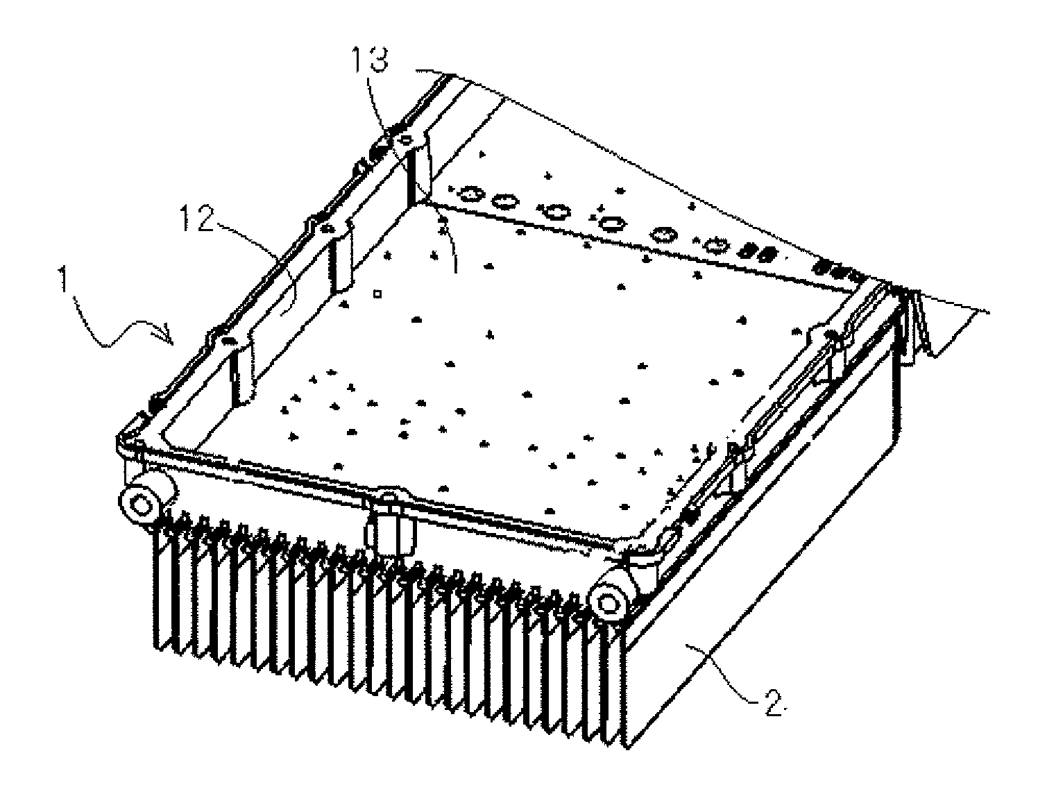
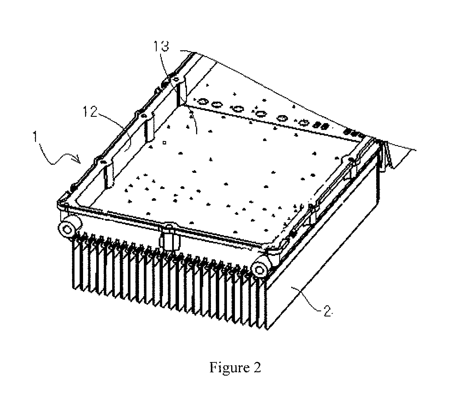
[0066]Refer to FIG. 2 and FIG. 3. A Heat Dissipating Enclosure 1 consists of an upper wall and a plurality of Side Walls 12. The upper wall and Side Walls forms an Outer Wall 13. A plurality of cooling fins is cast into Outer Wall 13.

[0067]Further refer to FIG. 3, Outer Wall 13 is provided with a plurality of cooling fins which are configured with a same interval and in parallel to each other.

[0068]According to the above descriptions and figures, it is clear that the cooling fins are cast into the heat dissipating enclosure with out any bonding agent. Therefore, manual bonding process could be eliminated, which greatly increases the production efficiency and makes it possible for automatical production. Moreover, it also improves heat-conducting property and fastening reliability.

[0069]In an emb...


PUM


Abstract

The invention discloses a heat dissipating enclosure with integrated cooling fins comprising a heat dissipation enclosure consisting of an upper wall and side walls, and the upper wall and side walls forms an outer wall. A plurality of cooling fins is connected to the outer wall. The bottom of the cooling fins is embedded and cast inside the heat dissipation enclosure, so the technical problem that the bonding agent used on the cooling fins is not beneficial for dissipating of heat is resolved, and the thermal dissipation efficiency is increased.

Description

TECHNICAL FIELD[0001]The present invention relates to the field of heat-sinks, in particularly, to a heat dissipating enclosure with integrated cooling fins having high thermal dissipation efficiency.BACKGROUND OF THE INVENTION[0002]With the development of the electronic techniques, heat generation of the electronic devices becomes larger and larger along with the increase of the power they use; this brings a higher standard of requirement for the related heat dissipation needs. Furthermore, the outdoor electronic devices are designed to resist water, wind and all other atmospheric events. The housings of outdoor electronic devices are mostly made of the nonferrous alloy casting, a large part of them are made by die casting. The internal space and features of the housing are designed to host and protect the PCB (Printed Circuit Board) or other functional components. Generally, a plurality of cooling fins is built on the outer surfaces of the housing to reduce the temperature that is...

Claims


Application Information

Patent Timeline
IPC IPC(8): F28F3/02H05K1/02
CPCH05K1/0203F28F3/02H01L23/3672H01L21/4882H01L2924/0002H01L23/3675H01L2924/00H01L21/67098H01L23/4093
Inventor CHEN, WEIGUOCAMPIDELLI, VERONIA
Owner MARCHESI METAL TECH SUZHOU
Why Eureka
Try Eureka