Fault detection and diagnosis in an induction motor

a fault detection and fault technology, applied in the field of induction motors, can solve the problems of increasing maintenance costs, adding cost and complexity to the machine, and inducing motors, so as to reduce computational power, reduce cost and complexity, and operate healthy

Inactive Publication Date: 2016-09-15
ROLLS ROYCE PLC
View PDF0 Cites 24 Cited by
  • Summary
  • Abstract
  • Description
  • Claims
  • Application Information

AI Technical Summary

Benefits of technology

[0015]The method of the first aspect of the present disclosure is advantageous as it may allow the detection of rotor and / or stator side faults in an induction motor using only the measured three-phase current. The need for additional sensors, for example voltage sensors, in order to detect rotor and / or stator side faults may be reduced or eliminated, thereby reducing the cost and complexity associated with fault detection in an induction motor.
[0045]Furthermore, the method according to the second aspect of the present disclosure may provide the benefit of allowing for detection of healthy operating conditions at an early stage of the fault detection and diagnosis procedure. Thus healthy operation can be detected at an early stage, eliminating and / or mitigating the need for the entire fault detection and diagnosis procedure to be carried out in order to determine healthy operation. This may reduce the computational power required to determine healthy operation, and may decrease the time interval between successive iterations of the fault detection and diagnosis procedure during healthy operation, thereby resulting in an increased chance of detecting a fault at an early stage.

Problems solved by technology

If electrical and thermal stress go undetected at an early stage, then they can lead to electrical (stator side) or mechanical (rotor side) failure, which may cause irreversible damage to the induction motor, and may result in increased maintenance costs.
However the need for such a bespoke sensing arrangement adds cost and complexity to the machine.
It has been found to be problematic to identify with certainty fault signatures that may be of particularly small magnitude at higher frequencies.

Method used


Image

  • Fault detection and diagnosis in an induction motor
  • Fault detection and diagnosis in an induction motor
  • Fault detection and diagnosis in an induction motor

Examples


Embodiment Construction

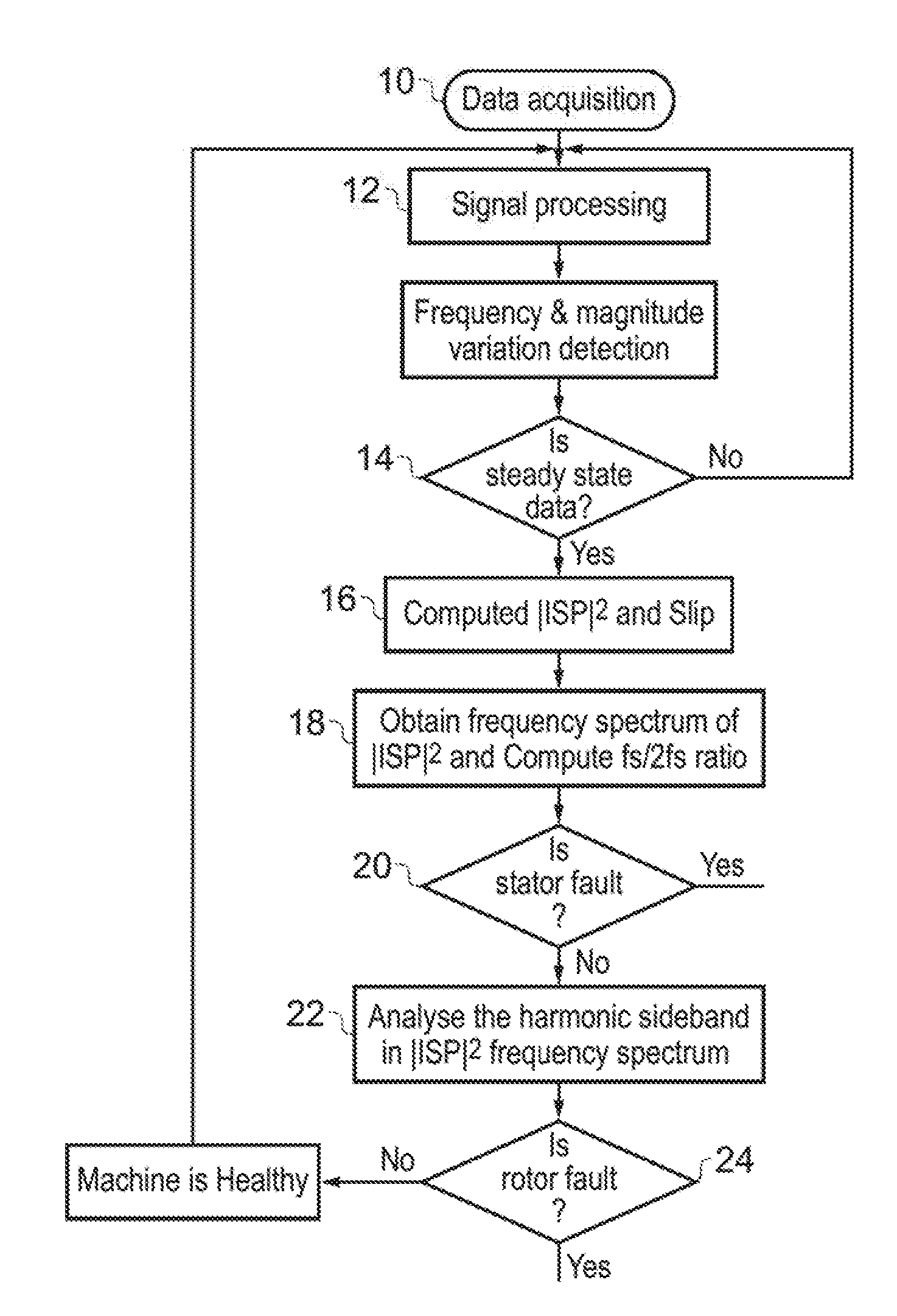
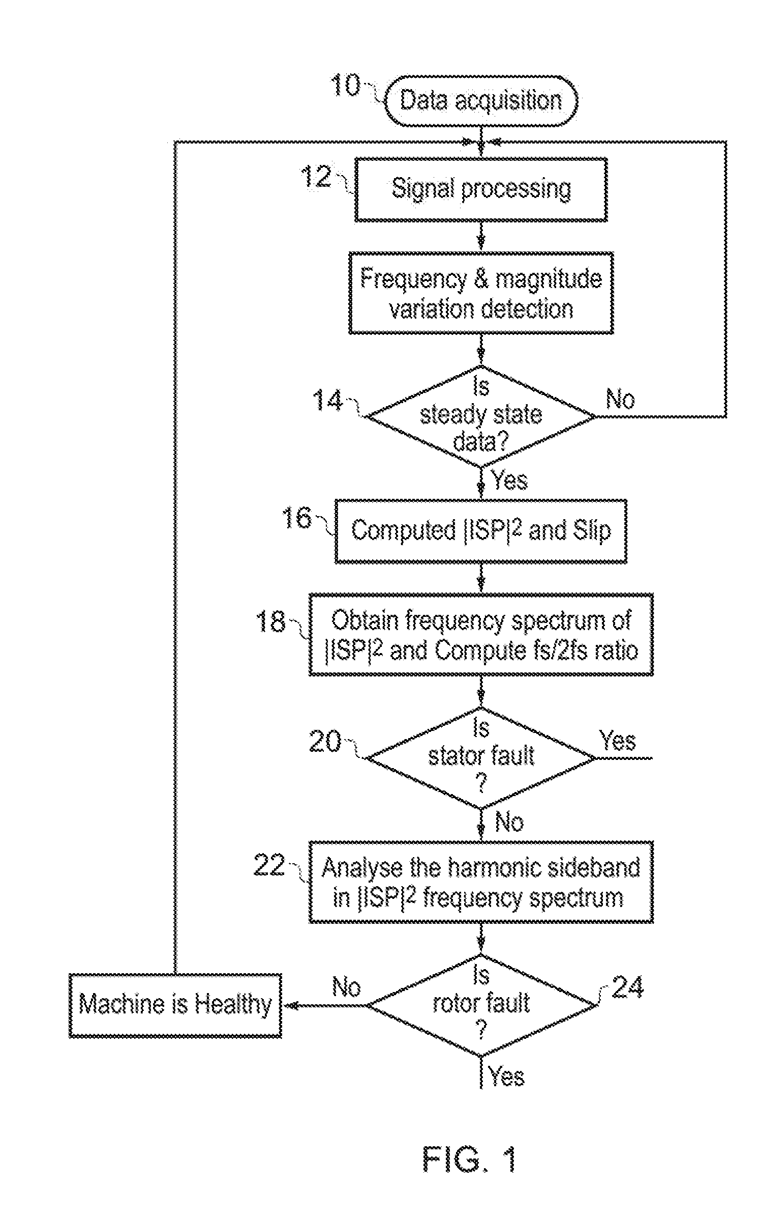
[0079]A method of detecting rotor and / or stator faults in an induction motor according to a first aspect of the present disclosure is described with reference to FIG. 1.

[0080]The method makes use of the Instantaneous Space Phase Square (|ISP|2) of the stator current. The |ISP|2 of stator current is calculated by converting the stator phase currents into phasors and then obtaining the square root for the squared sum of the three phase current phasors. The procedure for obtaining the |ISP|2 is given below, and utilises the stator phase currents P1, P2, and P3, for phases a, b, and c, respectively.

P1=Iasin(ωt−φ1)*(cos(0)+jsin(0))   (1)

P2=Ibsin(ωt−φ2)*(cos(2π / 3)+jsin(2π / 3))   (2)

P3=Icsin(ωt−φ3)*(cos(−2π / 3)+jsin(−2π / 3))   (3)

|ISP|2=(√(real(P1+P2+P3)2+img(P1+P2P3)2))2   (4)

[0081]The |ISP|2 has both DC and AC components, which are given by the following equations respectively:

DC=½[Ia2+Ib2Ic2]+½[IaIbcos(φ2+φ1)+IaIccos(φ3−φ1)+IbIccos(φ2−φ3)   (5)

AC=−½[Ia2cos(2ωt−2φ1)+Ib2cos(2ωt−2φ2)+Ic2cos(2...


PUM


Abstract

A method of detecting rotor and / or stator side faults in an induction motor. Signals indicative of three-phase stator currents of the induction motor are acquired (10) and converted (16) into three-phase current phasors. The three-phase current phasors are combined (16) to obtain a quantity having a DC component and an AC component. A frequency spectrum of the AC component is obtained (18) and compared (20,22) to a frequency spectrum of the AC component under healthy operating conditions in order to determine the presence of a rotor and / or stator side fault in the induction motor

Description

[0001]This disclosure claims the benefit of UK Patent Application No. 1503930.8, filed on 9 Mar. 2015, which is hereby incorporated herein in its entirety.BACKGROUND OF THE INVENTION[0002]This disclosure relates to induction motors, and in particular to methods of fault detection and diagnosis in an induction motor.[0003]Conventional induction motors operate via a multi-phase stator ac winding and a rotor. When in use, an alternating current supplied to the stator winding causes a magnetic field to form. Due to the alternating nature of the current supplied to the stator winding, the magnetic field rotates in time with the oscillations of the current. Relative motion between the magnetic field and the induction motor's rotor induces a current in the rotor, which in turn creates a magnetic field that opposes the change in current through the rotor. The rotor thereby rotates in the same direction as the rotating magnetic field formed by the stator winding. The rotor and the magnetic f...

Claims


Application Information

Patent Timeline
Patent Type & Authority Applications(United States)
IPC IPC(8): G01R31/34
CPCG01R31/346H02P29/0241
Inventor ATHIKESSAVAN, SUBASH CHANDARNADARAJAN, SIVAKUMARGUPTA, AMIT KUMARPANDA, SANJIB KUMARGAJANAYAKE, CHANDANA JAYAMPATHI
Owner ROLLS ROYCE PLC
Why Eureka
Try Eureka