Mounting unit and hair cutting appliance

a hair cutting and mounting unit technology, applied in the direction of metal working devices, etc., can solve the problems of complicating the handling of such a hair cutting appliance, not addressing shaving performance peculiarities and practical use aspects, and achieving the effect of avoiding time-consuming assembly steps, avoiding internal pollution of joints, and increasing flexibility

Active Publication Date: 2016-09-22
KONINKLJIJKE PHILIPS NV
View PDF14 Cites 9 Cited by
  • Summary
  • Abstract
  • Description
  • Claims
  • Application Information

AI Technical Summary

Benefits of technology

[0053]A living hinge may also be regarded as flexure bearing that is made from the same material as the parts that are connected in pivoting manner by the living hinge. It is further preferred in this regard that all pivots of the four-bar linkage mechanism are arranged as living hinges, particularly as film hinges. Film hinges or thin-film hinges may be manufactured, for instance, via an injection molding process. Consequently, at least one of the pivots and the respective neighboring parts connected by the pivot can be produced from basically the same material in an integral manner. This arrangement may further ensure that substantially no (mechanical) play is present in the pivots. Mechanical joints that are composed of separate components are typically designed in a clearance-fit manner including a defined play so as to allow a smooth pivoting motion. Moreover, film hinges may further have the advantage that any (internal) pollution of the joints can be prevented. According to another advantageous embodiment at least the first arm, the second arm and the connecting bar of the four-bar linkage mechanism and their respective base pivots and top pivots are integrally formed as a single piece.
[0054]This may be beneficial insofar as the four-bar linkage mechanism can be produced in basically a single production step. Particularly, time-consuming assembly steps can be avoided. It is further preferred in this regard that also the base of the four-bar linkage mechanism is at least partially integrated into the single piece shape.
[0055]Generally, it is desired that the linkage mechanism may be arranged to swivel about an axis that is parallel to the pivots defined by the film hinges. Film hinges are, on the one hand, basically designed for pivoting or swiveling about an axis that is defined by a thinned material section. However, since film hinges as such are typically made from considerably elastic material, the film hinges may also be moved, bent or deflected in other ways in response to respective external loads. Consequently, the cutting unit can be guided at the skin with far more flexibility, compared to conventional pivoting mechanisms for the cutting units of hair cutting appliances. In yet another embodiment, the four-bar linkage mechanism is an integrally formed injection molded plastic part. Preferably, plastic resins, such as polyethylene, polypropylene and similar materials having a sufficient fatigue resistance, may be used and processed for manufacturing the integrated four-bar linkage mechanism.

Problems solved by technology

The cutting appliance known from WO 2013 / 150412 A1 is particularly suited for both trimming and shaving operations but does not address shaving performance peculiarities and practical use aspects for hair cutting operations.
This may complicate the handling of such a hair cutting appliance.
Moreover, it has been observed that several users apply shaving devices also for styling operations, e.g. for precisely shaping an actual beard form or sideburns which may pose a further challenge.

Method used


Image

  • Mounting unit and hair cutting appliance
  • Mounting unit and hair cutting appliance
  • Mounting unit and hair cutting appliance

Examples


Embodiment Construction

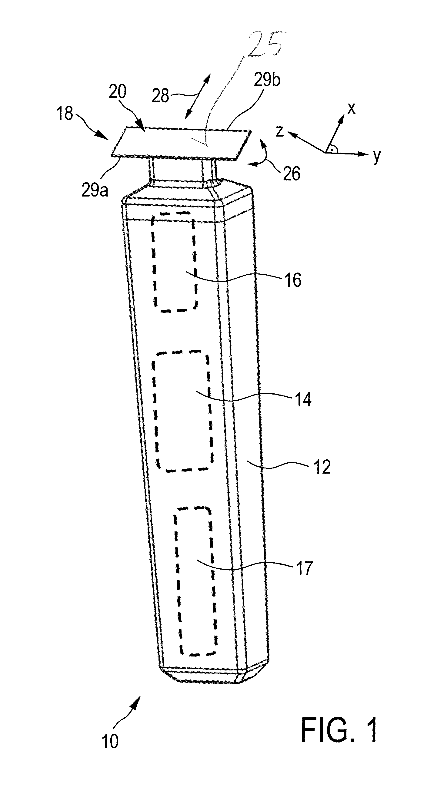
[0086]FIG. 1 schematically illustrates, in a simplified perspective view, an exemplary embodiment of a hair cutting appliance 10, particularly an electric hair cutting appliance 10. The cutting appliance 10 may include a housing 12, a motor indicated by a dashed block 14 in the housing 12, and a drive mechanism indicated by a dashed block 16 in the housing 12. For powering the motor 14, at least in some embodiments of the cutting appliance 10, an electrical battery, indicated by a dashed block 17 in the housing 12, may be provided, such as, for instance, a rechargeable battery, a replaceable battery, etc. However, in some embodiments, the cutting appliance 10 may be provided with a power cable for connecting a power supply. A power supply connector may be provided in addition or in the alternative to the (internal) electric battery 17.

[0087]The cutting appliance 10 may further comprise a cutting unit 18. At the cutting unit 18, a blade set 20 may be attached to the hair cutting appl...


PUM


Abstract

The present invention relates to a hair cutting appliance (10) comprising a mounting unit (30) for coupling a cutting unit (18) and a housing (12) thereof, and to a mounting unit (30), the mounting unit (30) comprising a swivel mechanism (32) comprising a base portion (38) arranged to be coupled to a housing (12), and a top portion (46) arranged to be coupled to a cutting unit (18), wherein the base portion (38) and the top portion (46) are movable with respect to each other, such that, during operation, the cutting unit (18) is pivotably supported by the swivel mechanism (32), wherein the swivel mechanism (32) defines a virtual pivot axis (p) for the cutting unit (18), the virtual pivot axis (p) being substantially parallel to a cutting edge (29) of the cutting unit (18),wherein, in a first state (I) of the swivel mechanism (32) in which the cutting unit (18) is adapted for shaving, the virtual pivot axis (p) is located at a first position (p) with respect to the cutting unit (18), and wherein, in a second state (II) of the swivel mechanism (32) in which the cutting unit (18) is adapted for styling, the virtual pivot axis (p) is located at a second position (p2) with respect to the cutting unit (18) that is different from the first position (p2).

Description

FIELD OF THE INVENTION[0001]The present disclosure relates to a hair cutting appliance, particularly to an electrically operated hair cutting appliance and more particularly to a mounting unit for coupling a cutting unit and a housing of a hair cutting appliance. The cutting unit may comprise a blade set, and may be arranged to be moved through hair in a moving direction to cut hair. The blade set may comprise a stationary blade and a movable blade, wherein the movable blade may be moved with respect to the stationary blade so as to cut hair trapped there between.BACKGROUND OF THE INVENTION[0002]EP 1 621 299 A1 discloses a dry shaver comprising a grip to be grasped by a user's hand, a shaving head being supported to said grip and carrying a foil cutter unit composed of an outer foil and an inner cutter driven to move relative to said outer foil in hair shearing engagement therewith, wherein said outer foil is elongated to have a length and a width, and being arcuately curved along i...

Claims


Application Information

Patent Timeline
Patent Type & Authority Applications(United States)
IPC IPC(8): B26B19/38B26B19/04
CPCB26B19/048B26B19/3846B26B19/042B26B19/063B26B21/225
Inventor MOLEMA, JEROENAITINK, ALBERT JANTUIJP, BRAMLOUWSMA, HENDRIK KLAASSTAPELBROEK, MARTINUS BERNARDUSVAN DER SCHEER, ROBBERT FREERK JOHAN
Owner KONINKLJIJKE PHILIPS NV
Why Eureka
Try Eureka