Autonomous airbag system for unmanned aerial vehicles

an airbag system and unmanned aerial vehicle technology, applied in the field of flying devices, can solve the problems of uncontrollable or limited control landing of the uav, relative slow and relatively fast movement of the uav

Inactive Publication Date: 2016-09-22
SHARPER SHAPE
View PDF12 Cites 16 Cited by
  • Summary
  • Abstract
  • Description
  • Claims
  • Application Information

AI Technical Summary

Benefits of technology

[0013]In an embodiment of the present disclosure, the airbag control unit is further configured to automatically deploy the airbag cushion, due to at least one of: a mechanical failure in the UAV, an electrical failure in the UAV, a communication error, a software error, a remote pilot failure, and a remote pilot intentional act.
[0014]In an embodiment of the present disclosure, the airbag control unit is further configured to inflate the airbag cushion when the UAV is about to collide with an object, even if the momentum of the UAV is below the threshold momentum value but the UAV has determined that distance to an object is too small, i.e. below a threshold distance value. This can be used for example in a case where the UAV is stationary but another object is about to collide with it.
[0015]In an embodiment of the present disclosure, the airbag control unit is further configured to deflate the airbag cushion after the expiry of a predetermined time period from the collision. In a yet another embodiment, the AAU further comprises at least one of an accelerometer and a pressure sensor.
[0016]According to another aspect of the disclosure, it relates to an unmanned aerial vehicle comprising at least one autonomous airbag unit as described above. The UAV may also comprise more than one AAUs, such as two, three, four or five AAU's. In this case, the AAU's are preferably each provided with communication means for interacting with each other.

Problems solved by technology

Further, some of the UAV's may move relatively slowly and others relatively fast.
A typical UAV has a complex arrangement and an error situation therein may lead to uncontrolled or limitedly controlled landing of the UAV.
If the UAV, for one reason or other, hits another UAV, a vehicle, a building or a human, it might cause a lot of destruction.
However, the parachutes may result in uncontrolled landing of the UAV to an arbitrary place, and may lead the UAV to collide in midair with other aircraft.
In case the emergency landing occurs in areas with people, driving cars, or e.g. nuclear facility, the impact of the UAV may cause death, accident, or even a major disaster.
However, in case of UAV, there is no such structure absorbing energy, that would enable an airbag launch triggered by at-the-time-of-collision deceleration.
Further, as the weight of the UAV is critical and must be minimized, it is not feasible to create a frame optimized to absorb energy in an UAV.

Method used


Image

  • Autonomous airbag system for unmanned aerial vehicles
  • Autonomous airbag system for unmanned aerial vehicles
  • Autonomous airbag system for unmanned aerial vehicles

Examples


Embodiment Construction

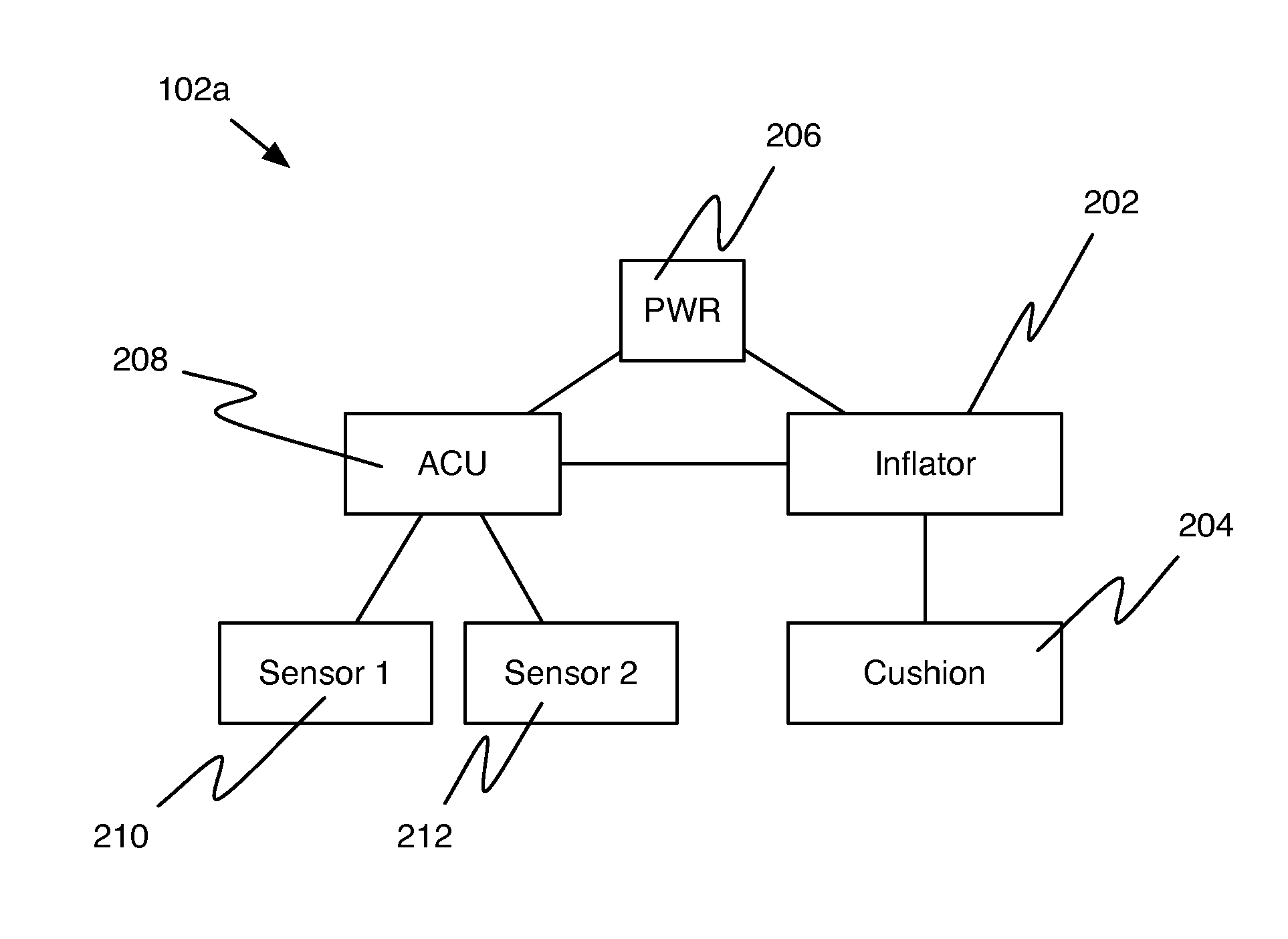
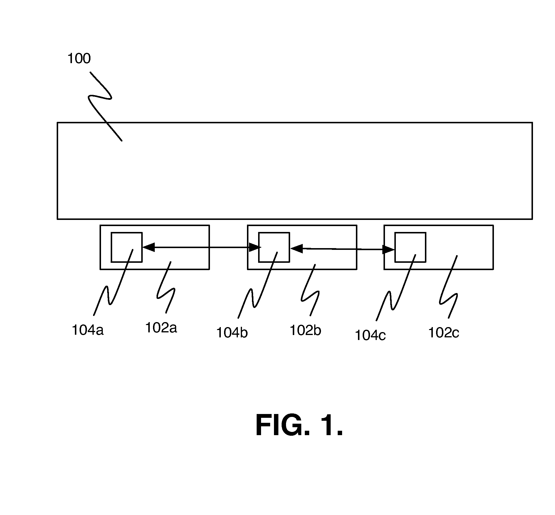
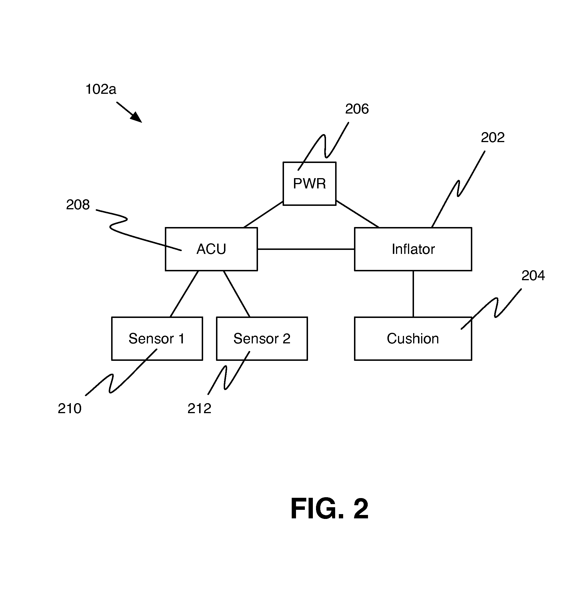
[0032]Referring now to the drawings, particularly by their reference numbers, FIG. 1 is an illustration of an unmanned air vehicle (UAV) 100 including here autonomous airbag units (AAU) 102a, 102b and 102c (hereinafter collectively referred to as AAUs 102), in accordance with an embodiment of the present disclosure. The AAUs 102 are safety devices installed at a bottom portion of the UAV 100, for minimizing damage to an object when the bottom portion of the UAV 100 collides with the object. The AAUs 102 includes airbag cushions that are inflated, when the UAV 100 is about to collide with an object in the event of an emergency landing.

[0033]In a collision, a force acts upon an object for a given amount of time to change the object's velocity. The product of force (F) and time (t) is referred as impulse (I). The product of mass (m) and velocity change (delta v, Δv) is known as momentum change. In a collision the impulse encountered by an object is equal to the momentum change it exper...


PUM


Abstract

The present disclosure is related to an autonomous airbag unit (AAU) for an unmanned aerial vehicle (UAV). The AAU includes a first sensor configured to determine a speed of the UAV, a second sensor configured to determine a relative speed of the UAV in relation to an object with which the UAV is likely to collide, an airbag cushion, an inflator connected to the airbag cushion, and an airbag control unit, connected to the first and second sensors and inflator. The airbag control unit is configured to estimate a momentum of the UAV based on a speed of the UAV, determine if the momentum of the UAV exceeds a threshold momentum value, determine if the relative speed of the UAV in relation to the object exceeds a threshold relative speed, and enable the inflator to inflate the airbag cushion when the momentum and the relative speed exceeds respective threshold limits.

Description

CROSS-REFERENCE TO RELATED APPLICATIONS[0001]This application claims priority to, and the benefit of, U.S. Provisional Patent Application No. 61 / 972,522 the disclosure of which is incorporated herein by reference in its entirety.TECHNICAL FIELD[0002]The present disclosure relates to flying devices such as Unmanned Aerial Vehicle (UAV), and in particular, to safety features for UAV in case of emergency landing.BACKGROUND[0003]Unmanned aircrafts have been generally defined and identified by a number of different titles, for instance, UAV by Joint JAA and Euro control task-force, Unmanned Aircraft Systems (UAS) by European Commission and European Aviation Safety Agency (EASA), Remotely Piloted Aircraft Systems (RPAS) and Remotely Piloted Vehicles (RPV) by most militaries. The Unmanned Aerial System (UAS) may refer to the complete system including UAVs, ground control stations, data links, displays, and controls which together are used to operate the UAV.[0004]Examples of UAVs include, ...

Claims


Application Information

Patent Timeline
Patent Type & Authority Applications(United States)
IPC IPC(8): B64D25/00B64C13/16B64C39/02
CPCB64D25/00B64D2201/00B64C13/16B64C39/024
Inventor HEINONEN, TERO
Owner SHARPER SHAPE
Why Eureka
Try Eureka