
Systems And Methods Of Adaptive Thermal Control For Information Handling Systems

Active Publication Date: 2016-09-22
DELL PROD LP
View PDF10 Cites 27 Cited by
  • Summary
  • Abstract
  • Description
  • Claims
  • Application Information

AI Technical Summary

Benefits of technology

The disclosed systems and methods may eliminate the need to keep exact accounting for CPU temperature specs within a thermal table and vulnerability to changes in CPU thermal control parameters that may be implemented by a CPU manufacturer between different CPU devices. Additionally, the systems and methods may be implemented in a way that is CPU bin agnostic, without defining a separate Tier for each CPU bin and without defining fan control cooling setpoints for each CPU device. These technical effects may provide more efficient and flexible cooling solutions for CPU devices.

Problems solved by technology

Such cooling fans may be uncontrolled, i.e., running at full power whenever the information handling system is a powered on state.
However, cooling fans consume power, create noise, and create airflow, each of which becomes of greater concern in a data center where a plurality of information handling system platforms may be operating, e.g., as servers.
Occasionally, the requirements are incorrectly documented.
Other times, qualification sample parts are incorrectly programmed with faulty values, resulting in bad thermal settings in system manufacturer thermal control tables.
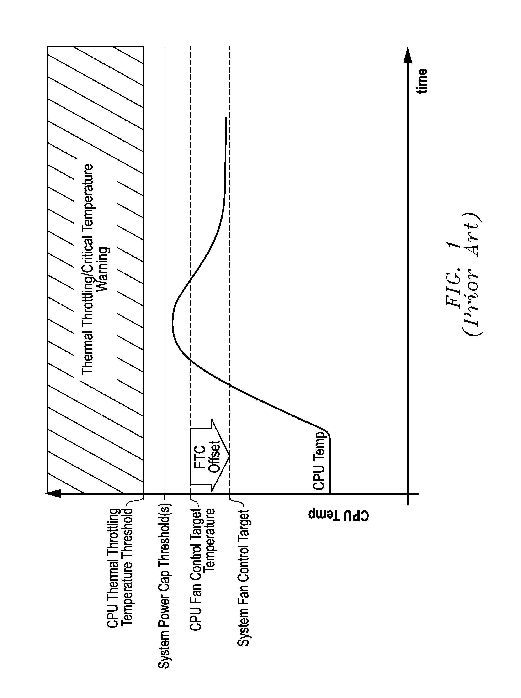
Thus, CPU thermal throttling temperature threshold may be exceeded in some cases due to system cooling capability limits even when the server BMC uses the retrieved CPU fan control target temperature setpoint value to trigger the system cooling fans.
This causes the CPU die operating temperature to overshoot or exceed both the system manufacturer power capping threshold temperature and the CPU thermal throttling temperature threshold, in turn causing CPU throttling and CPU thermal throttling activation before the CPU temperature is eventually controlled to the system manufacturer system fan control target setpoint temperature.
Consequently, CPU temperature and fan speed response are not stable, but rather oscillates as shown above and below the system manufacturer system fan control target setpoint temperature and may exceed the system manufacturer power capping threshold as shown, resulting in undesired CPU throttling initiated by the BMC.
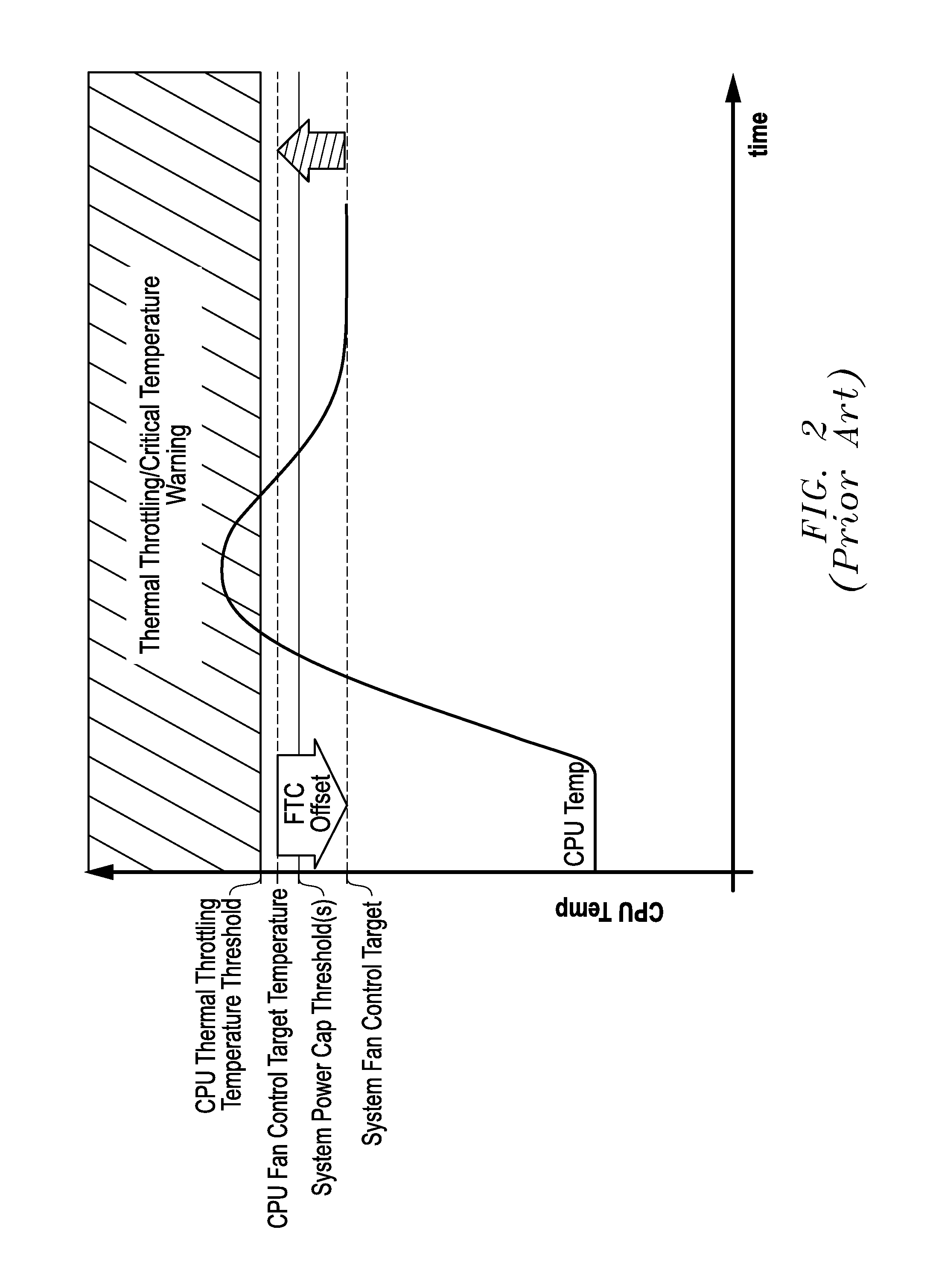
Consequently, CPU temperature is allowed to exceed the new CPU thermal throttling temperature threshold before reaching the system manufacturer power capping threshold temperature, which results in the undesirable consequences of a critical temperature warning and CPU thermal throttling activation described above.
As illustrated in FIGS. 1-4, there is a significant risk of having information handling system manufacturer-specified thermal control parameters / setpoints that aren't optimized for the CPU thermal control parameters / setpoints of the CPU devices that are actually installed and / or shipped with a given information handling system platform instantiation.
This can result in factory or field failures as a result of this problem.
Moreover, changes in CPU manufacturer thermal requirements and / or thermal parameter register values creates system manufacturer workload churn for the thermal control tuning and validation as well as driving additional builds and code validation.
Additionally, taking advantage of temperature relief provided by the CPU thermal profile results in risk of CPU thermal throttling activation.
The fan control target setpoint temperature from the CPU thermal profile increases with increasing CPU operating power to allow the CPU fan control target setpoint temperature value to eventually equal the specified CPU thermal throttling temperature threshold value for the CPU, which causes risk of CPU thermal throttling activation in the case of slight CPU temperature overshoot above the CPU thermal throttling temperature threshold value.

Method used


Image

  • Systems And Methods Of Adaptive Thermal Control For Information Handling Systems
  • Systems And Methods Of Adaptive Thermal Control For Information Handling Systems
  • Systems And Methods Of Adaptive Thermal Control For Information Handling Systems

Examples


Embodiment Construction

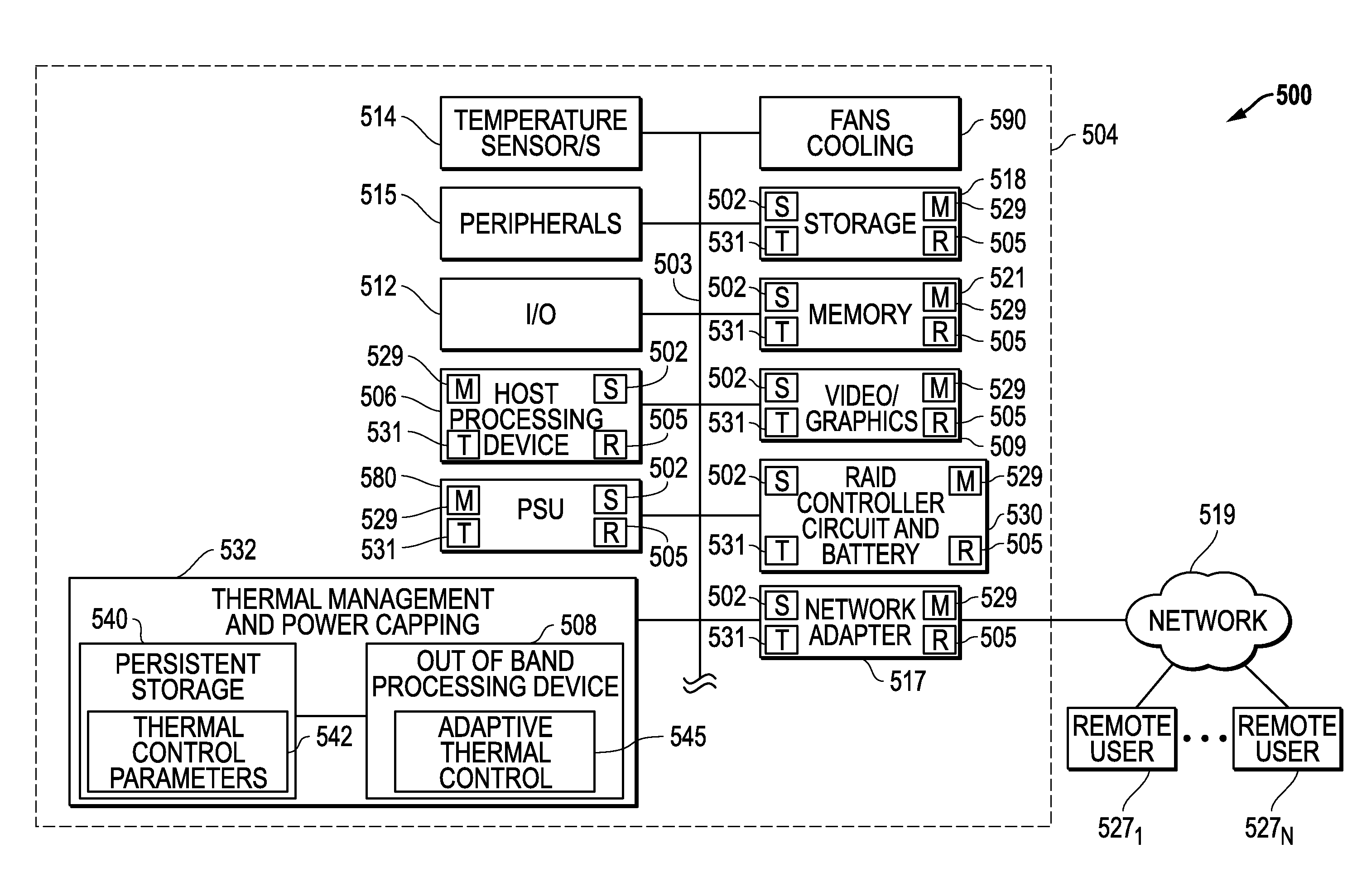
[0046]FIG. 5 illustrates one exemplary embodiment of an information handling system platform 500, configured in this embodiment as a server platform. As shown, system platform 500 includes heat-producing electrical components and one or more cooling fans 590 configured to cool the heat-producing components. The heat-producing components may be contained within an enclosure 504 (e.g., such as a 2U, 3U, 4U, etc. computer chassis) and cooled by the one or more cooling fan / s 590 in a manner as described below. Examples of heat-producing components illustrated in the embodiment of FIG. 5 include one or more in-band host processing devices 506 (e.g., CPU executing host operating system), video / graphics hardware (e.g., video card / s) 509, storage (e.g., one or more HDDs) 518, memory (e.g., RAM) 521, RAID controller 530, network adapter 517 and system power supply PSU 580, although other types and combinations of heat-producing components are possible. Additional components that may be prese...


PUM


Abstract

Systems and methods of adaptive thermal control are provided for information handling system platforms that may be implemented to automate and scale fan control settings by making the fan control settings relative to a reported component thermal control parameter value from a component of an information handling system platform, such as a CPU or other heat generating component. In one example, bounds for system use of vendor or component manufacturer-reported thermal control parameter values may be set for system cooling so as to confine use of these values within information handling system platform limits characterized by a manufacturer of an information handling system platform.

Description

FIELD OF THE INVENTION[0001]This invention relates generally to information handling systems and, more particularly, to thermal control for information handling systems.BACKGROUND[0002]As the value and use of information continues to increase, individuals and businesses seek additional ways to process and store information. One option available to users is information handling systems. An information handling system generally processes, compiles, stores, and / or communicates information or data for business, personal, or other purposes thereby allowing users to take advantage of the value of the information. Because technology and information handling needs and requirements vary between different users or applications, information handling systems may also vary regarding what information is handled, how the information is handled, how much information is processed, stored, or communicated, and how quickly and efficiently the information may be processed, stored, or communicated. The ...

Claims


Application Information

Patent Timeline
IPC IPC(8): G06F1/20G01K15/00
CPCG01K15/00G06F1/206G06F1/324Y02D10/00G05B2219/49216
Inventor LOVICOTT, DOMINICK ADAMSHABBIR, HASNAINTUNKS, ERIC
Owner DELL PROD LP
Learn More