
Microwave heating apparatus

a microwave heating and apparatus technology, applied in microwave heating, electric heating, electric/magnetic/electromagnetic heating, etc., can solve the problem of significantly lower power consumption of rf generators and antennas than conventional microwave technology, and achieve the effect of enhancing this

Inactive Publication Date: 2016-09-22
WAYV TECH
View PDF14 Cites 33 Cited by
  • Summary
  • Abstract
  • Description
  • Claims
  • Application Information

AI Technical Summary

Benefits of technology

This patent describes a cavity in a housing where RF radiation from multiple antennas is confined. The antennas are positioned at the edges or centre of the cavity, allowing for uniform heating of the items placed inside. The antennas are mounted on flexible printed circuit boards, which allow for a wider range of housing shapes. The technical effect of this invention is to provide a more efficient and uniform heating for RF processing.

Problems solved by technology

This means that the power consumption of the RF generator and antennas is significantly lower than conventional microwave technology.

Method used


Image

  • Microwave heating apparatus
  • Microwave heating apparatus
  • Microwave heating apparatus

Examples


Embodiment Construction

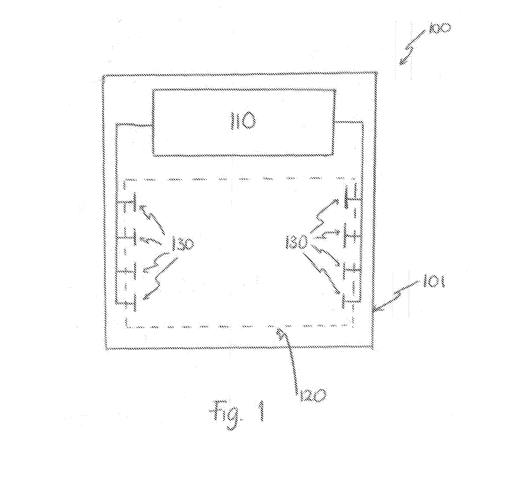
[0030]Referring first to FIG. 1, there is shown an exploded view of a microwave heating apparatus in accordance with the present invention. The microwave heating apparatus 100 comprises: a housing 101; a cavity 120 within the housing; a semiconductor RF generator 110; and a plurality of RF antennas 130. The plurality of RF antennas 130 are located within the cavity 120. The plurality of RF antennas 130 are coupled to the semiconductor RF generator 110 in order to receive at least one RF signal generated at the semiconductor RF generator.

[0031]In some embodiments, the semiconductor RF generator 110 may comprise a plurality of semiconductor RF generators, each of which is coupled to one or more of the plurality of RF antennas 130. Alternatively, a plurality of semiconductor RF amplifiers may be provided, each of which may be coupled to one or more of the plurality of RF antennas 130.

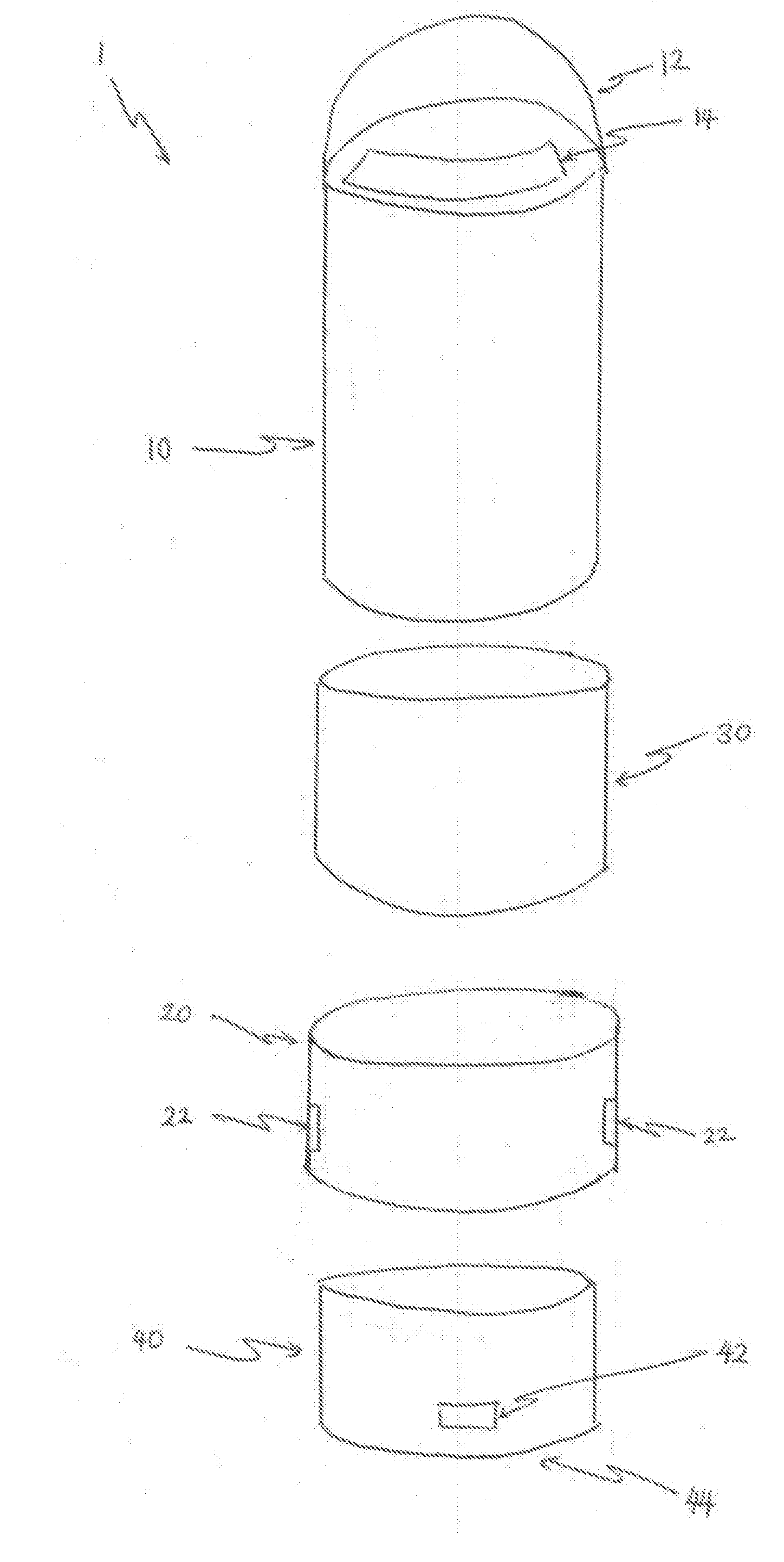
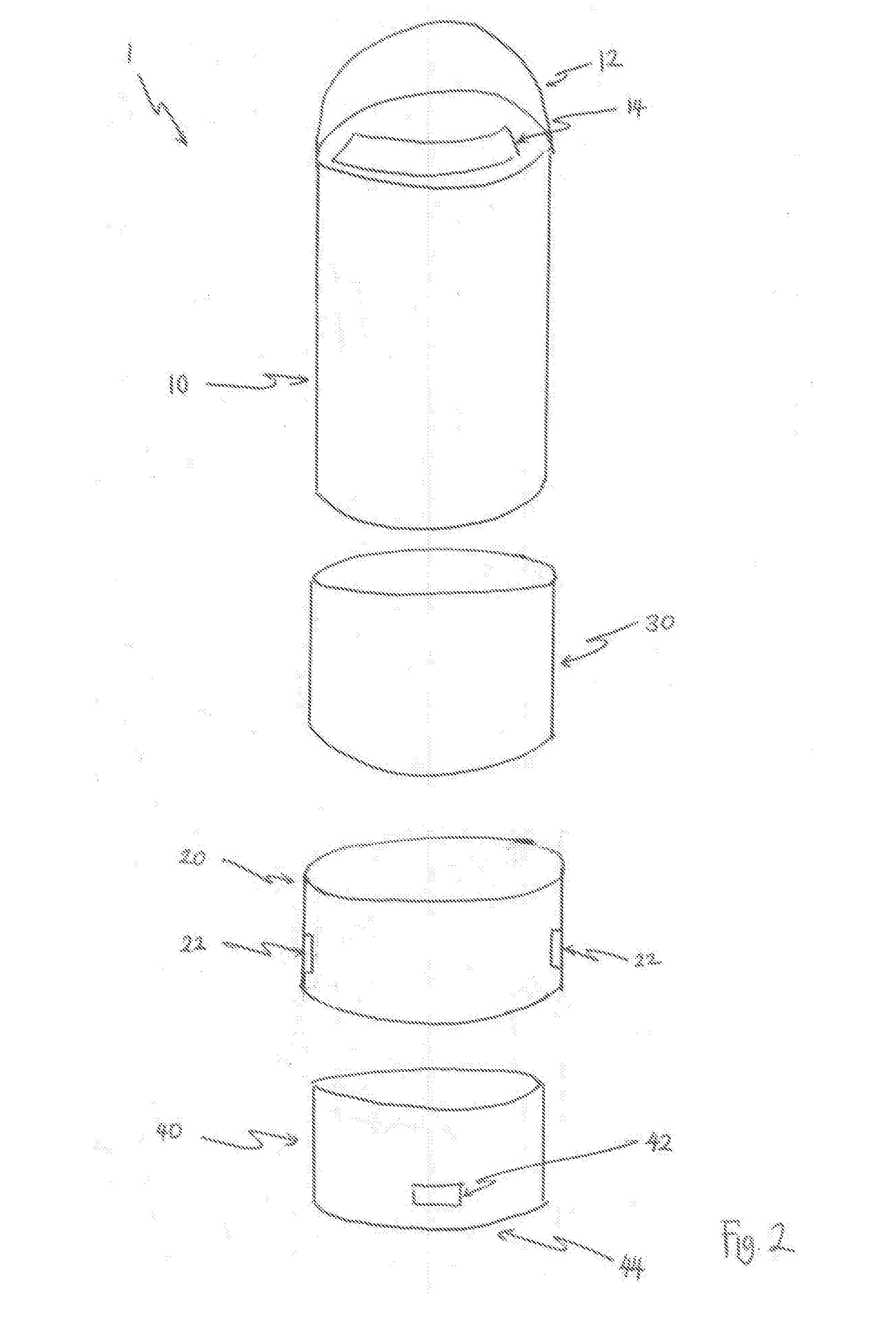
[0032]Referring next to FIG. 2, there is shown an exploded view of a microwave heating apparatus in acc...


PUM


Abstract

A microwave heating apparatus comprises: a housing, arranged to define a cavity; a semiconductor RF generator, configured to provide at least one RF signal; and a plurality of RF antennas, arranged in a distributed way within the cavity and configured to radiate the at least one RF signal from the semiconductor RF generator, such that items received in the cavity are dielectrically heated by the radiation.

Description

TECHNICAL FIELD OF THE INVENTION[0001]The present invention concerns an apparatus and method for microwave heating.BACKGROUND TO THE INVENTION[0002]Existing portable heating apparatus, primarily used for cooking or warming food and drink, can have difficulties in terms of efficiency and safety. For example, portable burning devices based on combustion of a fuel are inexpensive and simple to use but require good ventilation to avoid generation of toxic gases. Also, combustion-based devices can have difficulties in particular environments, particularly those where a flame is problematic, such as military or other dangerous situations.[0003]Electrical heating devices can avoid some of the latter problems but are often inefficient. It is difficult to provide a portable power supply that represents a balance between portability and usability. The larger the portable supply (such as a battery), the heavier and less portable the device becomes. Contrastingly, smaller batteries may mean tha...

Claims


Application Information

Patent Timeline
IPC IPC(8): H05B6/64H05B6/72
CPCH05B6/6467H05B6/725H05B6/6464H05B6/6402H05B6/6426H05B6/664H05B6/686H05B6/70H05B6/72Y02B40/00H05B6/80
Inventor ATHERTON, PAUL ANTHONYSTEVENS, PHILIP JOHN
Owner WAYV TECH
Learn More