
Lightweight composite lattice structures

a composite lattice and lightweight technology, applied in the field of lightweight composite lattice structures, can solve the problems of increasing complexity, reducing strength, and consuming a lot of time, and avoiding the effect of reducing strength

Inactive Publication Date: 2016-09-29
AEROSPACE HLDG CO LLC +1
View PDF10 Cites 12 Cited by
  • Summary
  • Abstract
  • Description
  • Claims
  • Application Information

AI Technical Summary

Benefits of technology

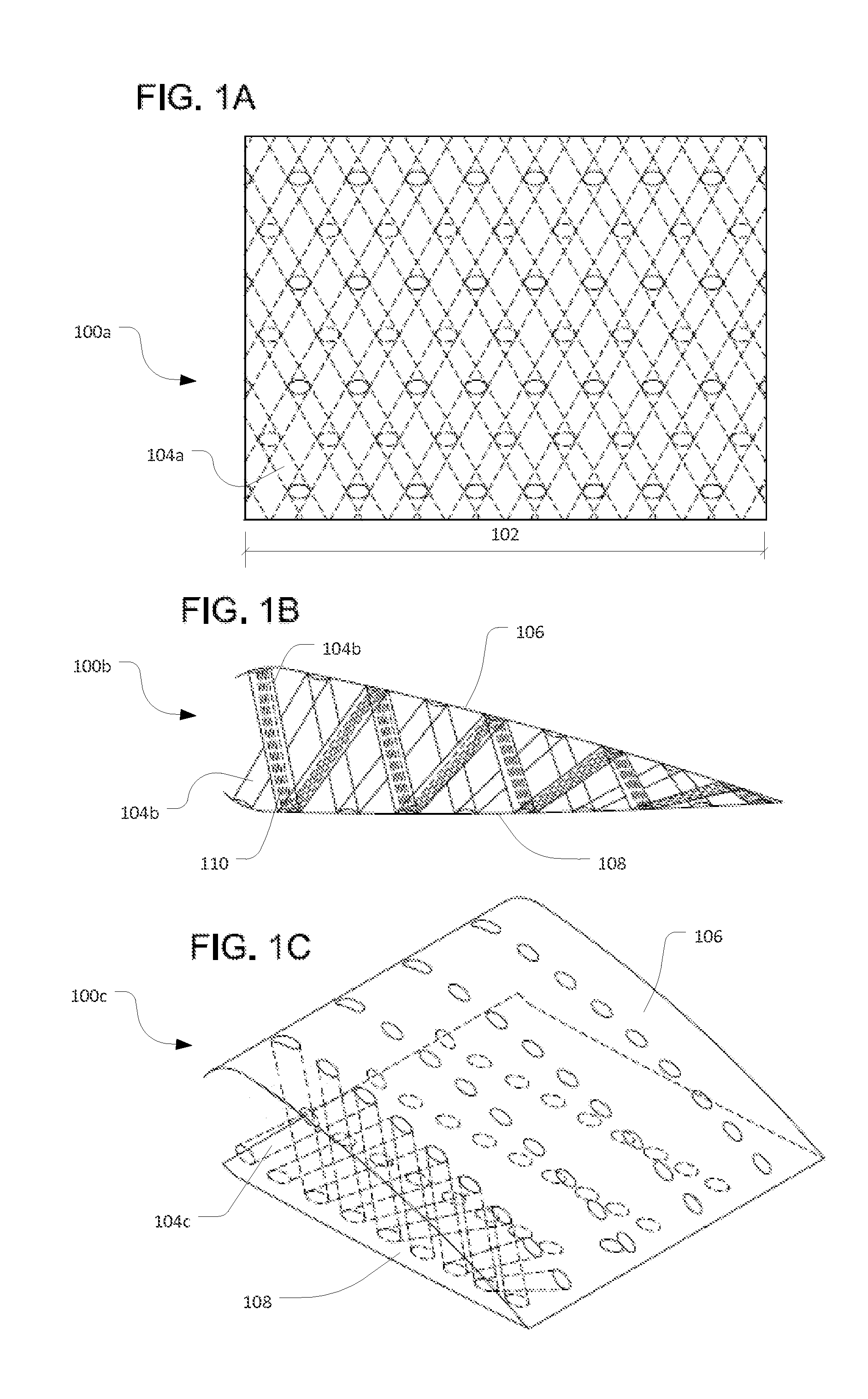
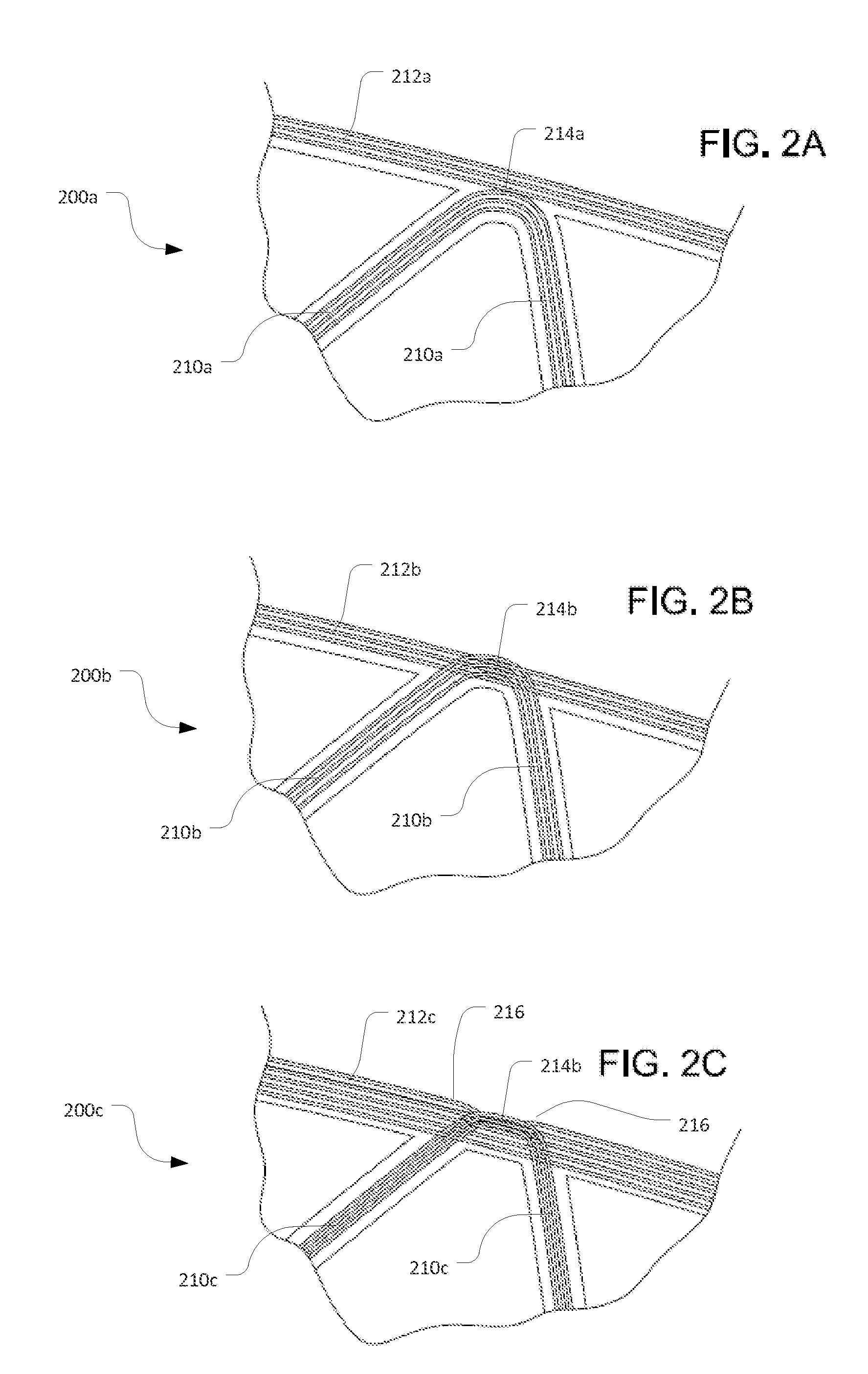
This patent describes a way to make a composite lattice structure by connecting face sheets with lattice members using fiber tows. The fiber tows can be interwoven with the face sheets and matrix material, creating a strong connection. The process involves using a removable pattern to secure the lattice members and face sheets, and then interfusing them with a fluid matrix material that is then cured to form a rigid matrix. When the pattern is removed, a composite lattice structure is formed. The technical effect is the creation of a composite lattice structure with strong fiber-matrix connections.

Problems solved by technology

However, composites tend to possess a variety of drawbacks that prevent adoption into all applications for which this ratio is important.
Composite beams may be extraordinarily strong in tension, but in compression may be subject to a variety of failure modes such as: matrix splitting, wherein the ends of a composite beam separate along planes between the fibers sheets and the beam splits down the middle; small-scale and large-scale buckling, wherein the individual fibers or the whole beam bends and fractures (respectively); or delamination, wherein the fibers may separate from one another along a shear plane between the fibers.
Composite construction tends to be expensive and time-consuming where the geometries of parts are complex.
Various parts of the construction process, for example cutting and attaching composite parts, may introduce surface imperfections which significantly diminishing strength.
Therefore, in conventional composite manufacturing, increasing complexity may be correlated with ever greater risk of part failure.

Method used


Image

  • Lightweight composite lattice structures
  • Lightweight composite lattice structures
  • Lightweight composite lattice structures

Examples


Embodiment Construction

[0019]In the following description, various embodiments will be described. For purposes of explanation, specific configurations and details are set forth in order to provide a thorough understanding of the embodiments. However, it will also be apparent to one skilled in the art that the embodiments may be practiced without the specific details. Furthermore, well-known features may be omitted or simplified in order not to obscure the embodiment being described.

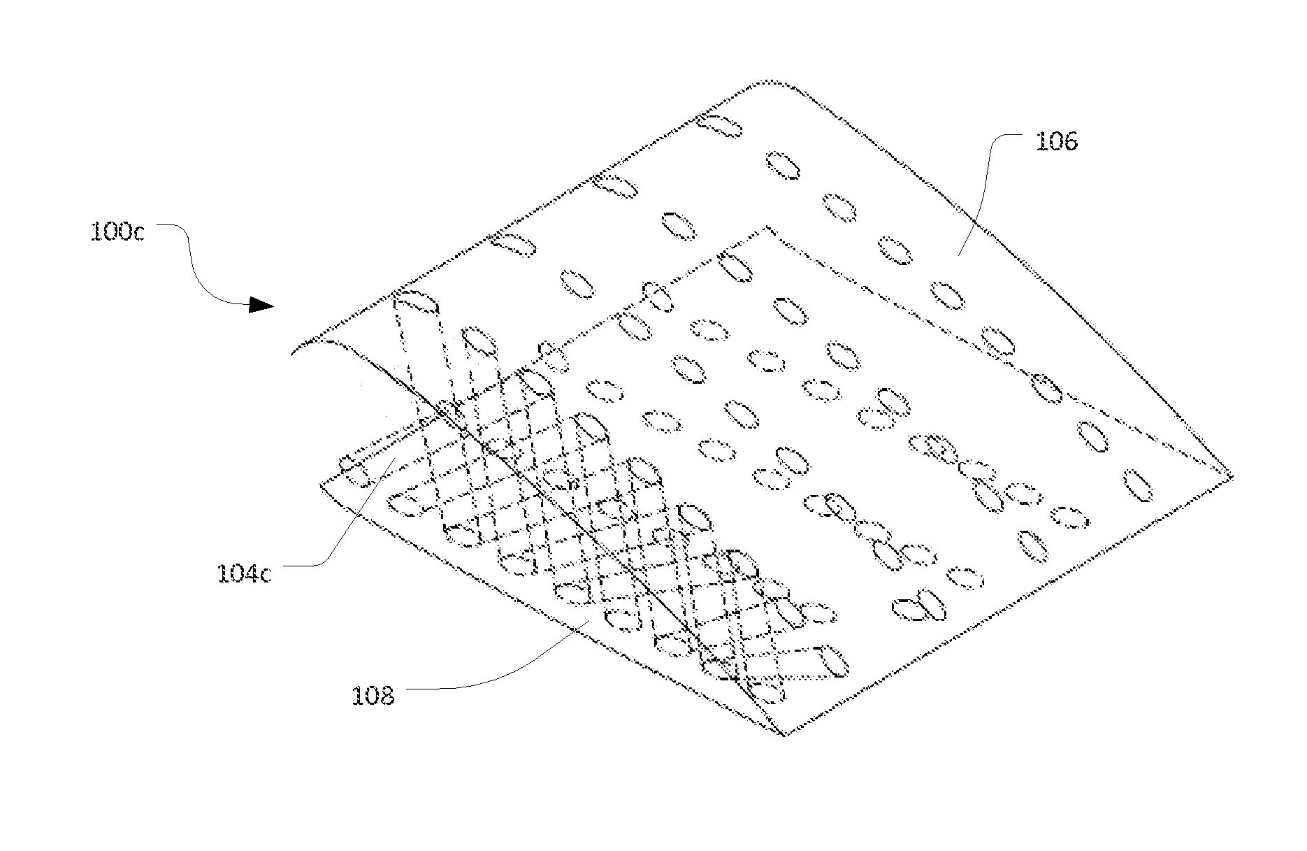
[0020]Various embodiments herein described are directed to lattice structures made of fiber-reinforced composite materials. The lattice structures have one or more face sheets connected with lattice members. One or more fiber tows create two or more lattice members in the lattice structure. Both or either of the lattice members and face sheets are a fiber-reinforced composite material. Some embodiments of the lattice members and face sheets can be formed as a single contiguous piece, and can be formed according to a method that...


PUM

PropertyMeasurementUnit
angleaaaaaaaaaa
angleaaaaaaaaaa
angleaaaaaaaaaa

Abstract

A composite lattice structure formed of one or more face sheets connected with lattice members, where the lattice members are formed of single or multiple contiguous fiber tows, and the lattice members and face sheets are interfused in a matrix.

Description

CROSS-REFERENCES TO RELATED APPLICATIONS[0001]This application is related to and incorporates by reference for all purposes the full disclosure of co-pending U.S. patent application Ser. No. ______, filed concurrently herewith, entitled “METHOD OF MANUFACTURING LIGHTWEIGHT COMPOSITE LATTICE STRUCTURES,” (Attorney Docket No. 97745-934356 (000101US)).BACKGROUND[0002]Fiber-reinforced composites are integrated into parts for high-strength / low-weight applications, such as aerospace structures, due to their high strength-to-weight ratio. However, composites tend to possess a variety of drawbacks that prevent adoption into all applications for which this ratio is important. Composite beams may be extraordinarily strong in tension, but in compression may be subject to a variety of failure modes such as: matrix splitting, wherein the ends of a composite beam separate along planes between the fibers sheets and the beam splits down the middle; small-scale and large-scale buckling, wherein the ...

Claims


Application Information

Patent Timeline
Patent Type & Authority Applications(United States)
IPC IPC(8): B32B7/08
CPCB32B2307/718B32B7/08B32B5/022B32B5/024B32B5/06B32B5/08B32B5/26B32B15/043B32B15/14B32B29/005B32B29/02B32B3/04B32B3/266B32B2260/021B32B2260/046B32B2262/0269B32B2262/101B32B2262/106B32B2262/14B32B2307/546B32B2419/00B32B2603/00B32B2605/18B29C70/342B29C70/443B29C70/446B29C33/52B29D99/0014B29C70/224B29K2101/10B29L2031/085B29C53/56B32B7/05Y02P70/50
Inventor CANTWELL, WESLEY JAMESUMER, REHAN
Owner AEROSPACE HLDG CO LLC
Learn More