Carrier bar and carrier bar assembly structure

a carrier bar and assembly structure technology, applied in the field of base carriers, can solve the problems of insufficient insertion and incorrect assembly of the carrier bar to a non-standard stay, and achieve the effect of improving the freedom of adjustment of the stay assembly position

Active Publication Date: 2016-09-29
CAR MATE MFG
View PDF9 Cites 10 Cited by
  • Summary
  • Abstract
  • Description
  • Claims
  • Application Information

AI Technical Summary

Benefits of technology

[0017]According to another aspect of the present invention, there is provided a carrier bar assembly structure including; a carrier bar having a shell and a lid; and a stay having a clamp mechanism, the shell being formed along a longitudinal direction and having an assembly opening and a positioning opening provided to extend toward a longitudinal end or a longitudinal center of the shell, a terminated end of the positioning opening being formed by the longitudinal end of the shell when the positioning opening extends toward the longitudinal end, the terminated end of the positioning opening being formed by the longitudinal center of the shell when the positioning opening extends toward the longitudinal center of the shell, the lid having an engagement portion engaged to the clamp mechanism inserted into the assembly opening, the lid being arranged oppositely to a direction of forming the positioning opening of the shell with respect to the assembly opening to seal a part of the assembly opening and the positioning opening by sliding toward the positioning opening, the assembly opening having an opening width and an opening length into which the head of the clamp mechanism is insertable, the positioning opening having an opening width, narrower than that of the assembly opening, along which the constricted portion is slidable, and an opening length longer than that of the assembly opening, the clamp mechanism having a head that is insertable into the assembly opening on a carrier bar assembly surface that supports the carrier bar and has a width wider than that of the positioning opening, and a constricted portion that is allowed to intrude into the positioning opening, wherein the clamp mechanism is engaged with the engagement portion of the lid when it is inserted into the assembly opening, so that the stay slides toward the positioning opening, and sliding of the lid is achieved.
[0018]In the carrier bar assembly structure described above, the lid and the shell may be provided with marks for recognizing where the stay is placed with respect to positioning means as the lid slides. As a result, it is possible to specifically recognize the stay assembly position relative to the carrier bar.
[0019]Using the carrier bar having the aforementioned characteristics, it is possible to suitably perform a stay assembly work and improve freedom in adjustment of the stay assembly position relative to the carrier bar.

Problems solved by technology

Sometimes, insertion may be insufficient, or the carrier bar may be erroneously assembled to a non-standard stay.

Method used


Image

  • Carrier bar and carrier bar assembly structure
  • Carrier bar and carrier bar assembly structure
  • Carrier bar and carrier bar assembly structure

Examples


Embodiment Construction

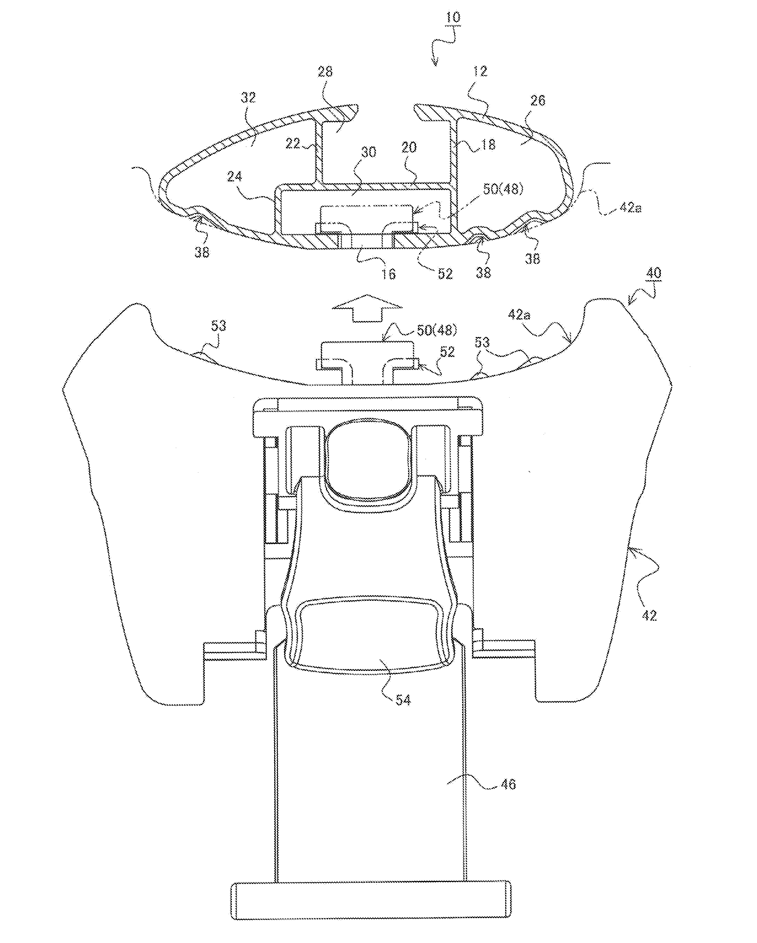
[0035]A description will now be made in detail for a carrier bar and a carrier assembly structure according to an embodiment of the invention with reference to the accompanying drawings.

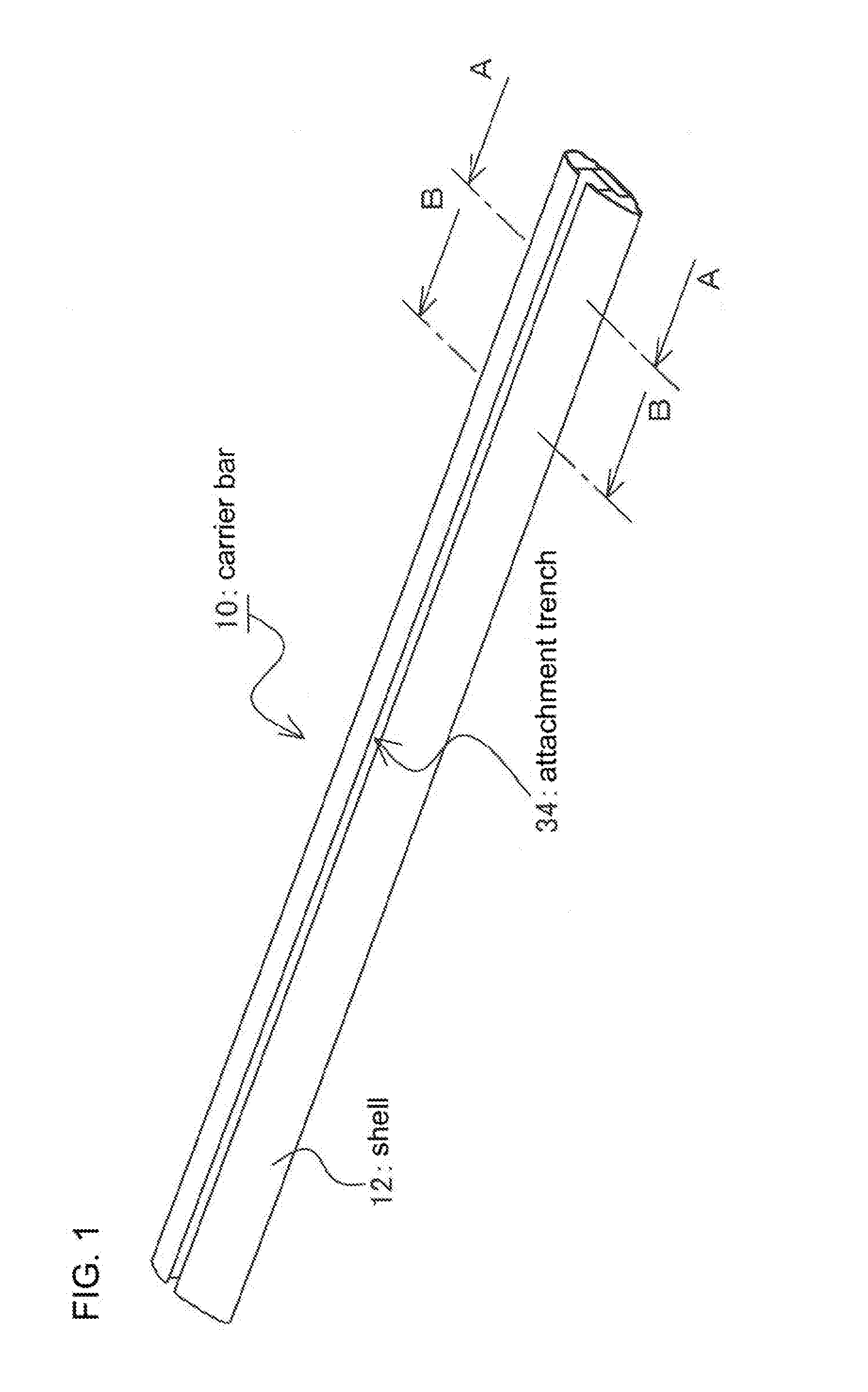
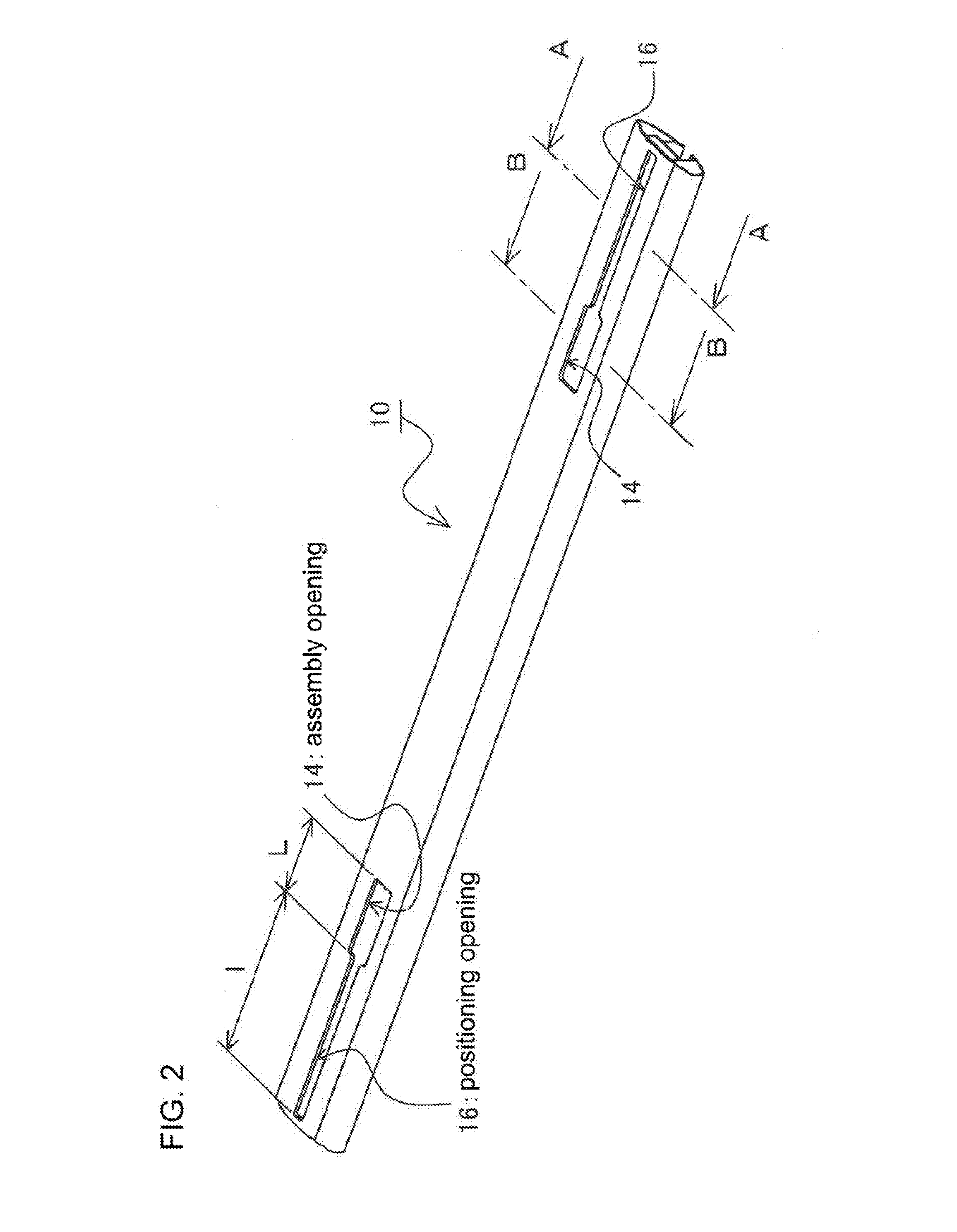
[0036]First, a carrier bar according to an embodiment of the invention will be described with reference to FIGS. 1 to 5. It is noted that FIG. 1 is a perspective view illustrating a carrier bar according to an embodiment by focusing on a plane side of the carrier bar, and FIG. 2 is a perspective view illustrating a carrier bar according to an embodiment by focusing on a bottom side of the carrier bar. In addition, FIG. 3 is a side view illustrating a cross section of the carrier bar according to an embodiment. Furthermore, FIG. 4 is a diagram illustrating a cross section take along a line A-A of FIG. 1 and FIG. 2, and FIG. 5 is a diagram illustrating a cross section taken along a line B-B.

[0037]The carrier bar 10 according to this embodiment includes, basically, a long shell 12, a plurality of partit...


PUM


Abstract

A carrier bar is provided, capable of enabling suitable assembly work of the stay and improving freedom in adjustment of stay assembly position relative to carrier bar, disclosed is a carrier bar having shell formed along longitudinal direction and hollow zones in cross-sectional structure so as to be assembled to stay by using a clamp mechanism having a head and a constricted portion to form a base carrier. Shell has assembly and positioning openings extending toward the longitudinal end of shell by using assembly opening as a basal end and having a terminated end formed by longitudinal end of shell. Assembly opening has an opening width and an opening length into which the head of clamp mechanism is insertable. Positioning opening has an opening width narrower than that of assembly opening, along which the constricted portion is slidable, and an opening length longer than that of assembly opening.

Description

TECHNICAL FIELD[0001]This invention relates to a base carrier installed to a vehicle roof, and more particularly, to a carrier bar of the base carrier and an assembly structure between the carrier bar and the stay.BACKGROUND ART[0002]A base carrier serving as a base of a system carrier has basic components such as a carrier bar, a stay for supporting the carrier bar, and a hook for fixing the stay to a vehicle.[0003]The basic components such as the carrier bar, the stay, and the hook may be designed dedicatedly to a certain vehicle model. However, in order to provide versatility within a limited range, an assembly adjustment mechanism is designed to allow for a maximum size of the installable vehicle model. For example, a carrier bar discussed in Patent Literature 1 is provided with a positioning opening for assembling the stay on the stay-assembled surface (lower surface) of the carrier bar in order to enable adjustment to the stay assembly position. As a result, the stay assembly ...

Claims


Application Information

Patent Timeline
Patent Type & Authority Applications(United States)
IPC IPC(8): B60R9/058
CPCB60R9/058B60R9/045B60R9/052
Inventor SATO, YUICHIKISAKA, DAISUKENAKAMURA, HISASHI
Owner CAR MATE MFG
Why Eureka
Try Eureka