A camera clamping and object supporting device for binocular vision shooting

A technology of binocular vision and supporting devices, which is applied in the direction of machines/stands, photography, supporting machines, etc. It can solve the problems of poor flexibility, high requirements for shooting environment, and low precision, and achieve automatic control, flexible control, and high precision. high effect

Pending Publication Date: 2019-01-25
HARBIN UNIV OF SCI & TECH
View PDF5 Cites 3 Cited by
  • Summary
  • Abstract
  • Description
  • Claims
  • Application Information

AI Technical Summary

Problems solved by technology

[0003] According to the present invention, most of the existing binocular vision detection support mechanisms adopt a mechanical structure, and manually adjust the position of the camera and the shooting object, which has low precision, poor flexibility, and high requirements for the shooting environment.

Method used


Image

  • A camera clamping and object supporting device for binocular vision shooting
  • A camera clamping and object supporting device for binocular vision shooting
  • A camera clamping and object supporting device for binocular vision shooting

Examples


Embodiment Construction

[0018] In order to make the purpose, technical solution and advantages of the present invention clearer, the present invention will be described below through specific implementation examples shown in the accompanying drawings. It should be understood, however, that these descriptions are exemplary only and are not intended to limit the scope of the present invention. Also, in the following description, descriptions of well-known structures and techniques are omitted to avoid unnecessarily obscuring the concept of the present invention.

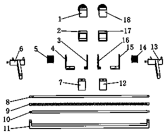
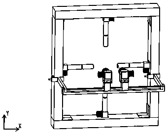
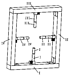
[0019] The specific structure and implementation mode of the present invention will be further described below in conjunction with the accompanying drawings. The structural composition of the present invention is as figure 1 , figure 2 and image 3 .

[0020] The present invention adopts following scheme:

[0021] Implementation example 1:

[0022] A camera clamping and object supporting device for binocular vision shooting, characteri...


PUM


Abstract

The invention discloses a camera clamping and object supporting device for binocular vision shooting, comprises a support rod I, a support rod II, a support rod III and a support rod IV, wherein the support rod and the electric push rod are connected with each other through an angle iron, the support rod and the electric push rod are connected with each other through screws, and the rotating rod is connected with an electric motor embedded in the electric push rod through a shaft sleeve. The camera clamping structure is fixed on the support rods II and IV through clips, and the two ends of thelead screw guide rails are respectively fixed on the ends of the clips. The sliding table is connected with a roller screw, the camera is connected with a camera sleeve, the camera sleeve is connected with a camera clamping bracket, the motor is connected with the camera sleeve through a hole in the camera clamping bracket, and the camera clamping bracket is connected with a motor embedded in thesliding table. The invention can realize the movement of the photographed object along the horizontal and vertical directions, as well as the adjustment of the rotation and the pitch angle, simultaneously can realize the movement and the pitch angle adjustment of the binocular vision camera along the horizontal and the vertical directions, and flexibly adjusts the relative position and the angleof the photographed object and the camera. The invention can be applied to the quality detection of the object surface and the three-dimensional reconstruction of the object surface.

Description

technical field [0001] The invention belongs to the technical field of machine vision, in particular to a camera clamping and object supporting device for binocular vision shooting. Background technique [0002] With the continuous development and progress of science and technology, machine vision has already replaced manual inspection of product surface quality in the processing and manufacturing of large-scale industrial products. The application of machine vision can greatly improve work efficiency and reduce detection errors. Although the monocular vision inspection has a simple structure, its detection accuracy is relatively low. For some products that require high quality accuracy, the use of binocular vision inspection has important practical significance. [0003] According to the present invention, most of the existing binocular vision detection support mechanisms adopt a mechanical structure, and the positions of the camera and the shooting object are manually adju...

Claims


Application Information

Patent Timeline
Patent Type & Authority Applications(China)
IPC IPC(8): G03B15/08F16M11/04F16M11/10
CPCG03B15/08F16M11/04F16M11/043F16M11/10
Inventor 张洪鑫张旭仇浩然
Owner HARBIN UNIV OF SCI & TECH
Why Eureka
Try Eureka