Roller-type one-way clutch and side plate

a one-way clutch and roller-type technology, applied in the direction of clutches, freewheel clutches, mechanical devices, etc., can solve the problems of low yield and failure to meet the demand for a reduction in manufacturing costs, and achieve the effect of reducing the quantity of materials used, improving yield and reducing manufacturing costs

Inactive Publication Date: 2016-09-29
NSK WARNER
View PDF1 Cites 4 Cited by
  • Summary
  • Abstract
  • Description
  • Claims
  • Application Information

AI Technical Summary

Benefits of technology

[0022]According to the roller type one-way clutch and the side plate in accordance with the present invention, the side plate has a non-circular shape, one end surface in the axial direction is annular, and at least a portion of the one end surface in the axial direction of the outer race is exposed in a state in which the side plate is secured. This arrangement makes it possible to reduce the quantity of a material used for the side plate and improve the yield, thus permitting a reduction in manufacturing cost.
[0023]According to the roller type one-way clutch and the side plate in accordance with the present invention, the side plate has a non-circular shape to reduce the quantity of the material used for the side plate, thus enabling the roller type one-way clutch to have a reduced weight.
[0024]Further, since the pocket adapted to be exposed beyond the side plate, it is possible to reduce the quantity of the material used for the side plate, improve the yield and ensure the function for discharging foreign substances from the pocket.

Problems solved by technology

Hence, there has been a problem in that a large quantity of a material is used and press-working the side plate results in a low yield, thus failing to meet the demand for a reduction in manufacturing cost.

Method used


Image

  • Roller-type one-way clutch and side plate
  • Roller-type one-way clutch and side plate
  • Roller-type one-way clutch and side plate

Examples


first embodiment

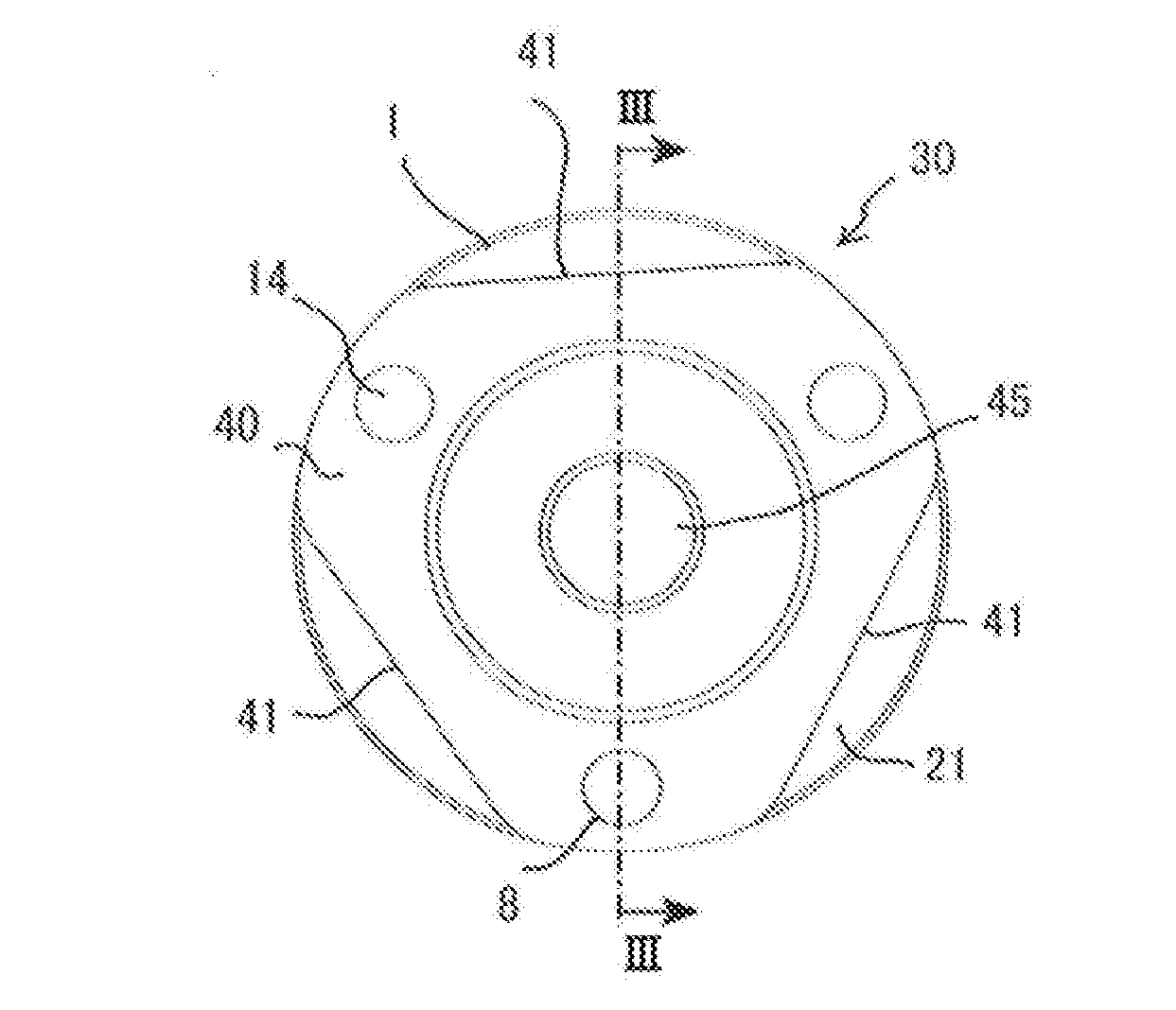
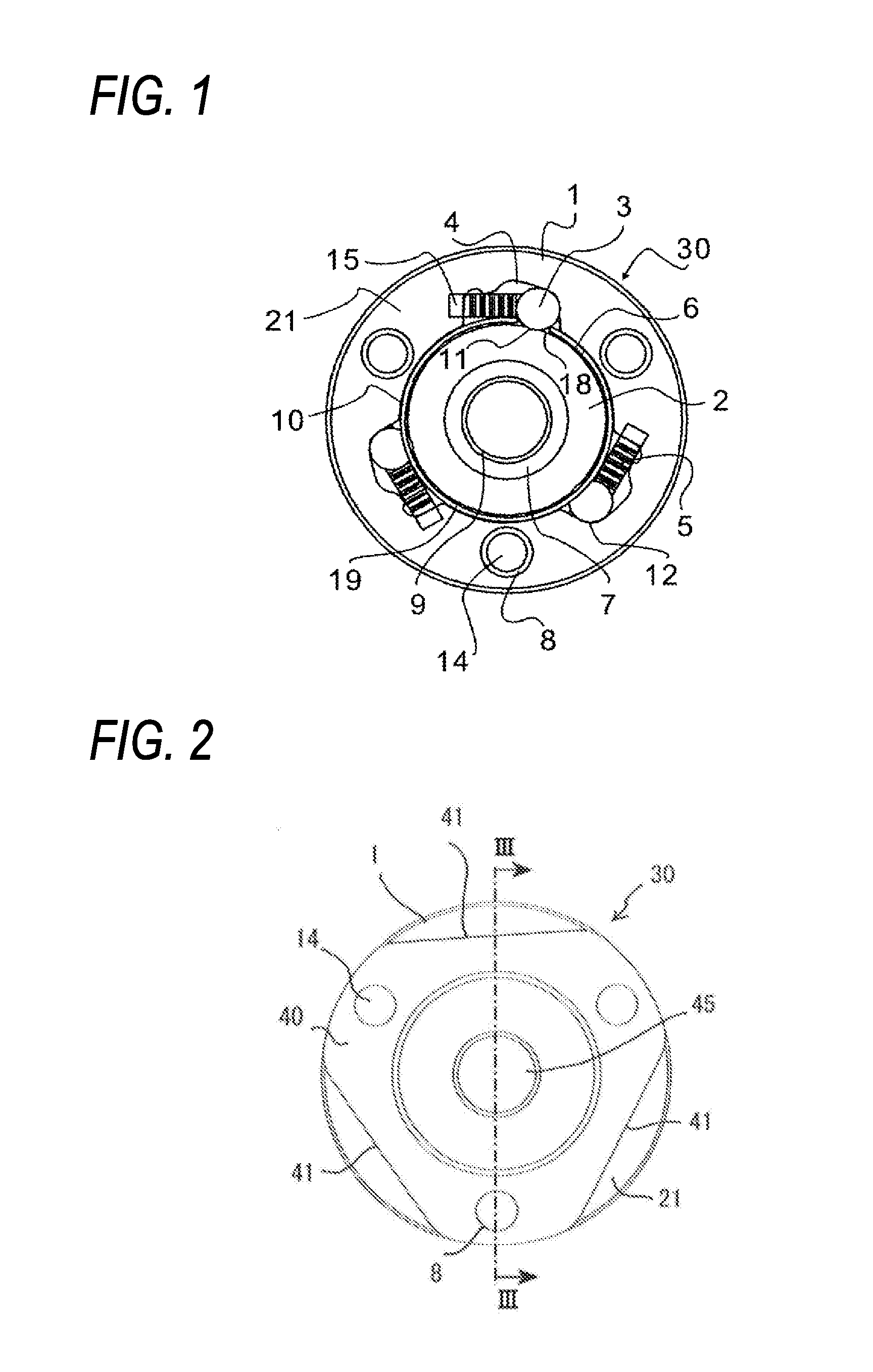
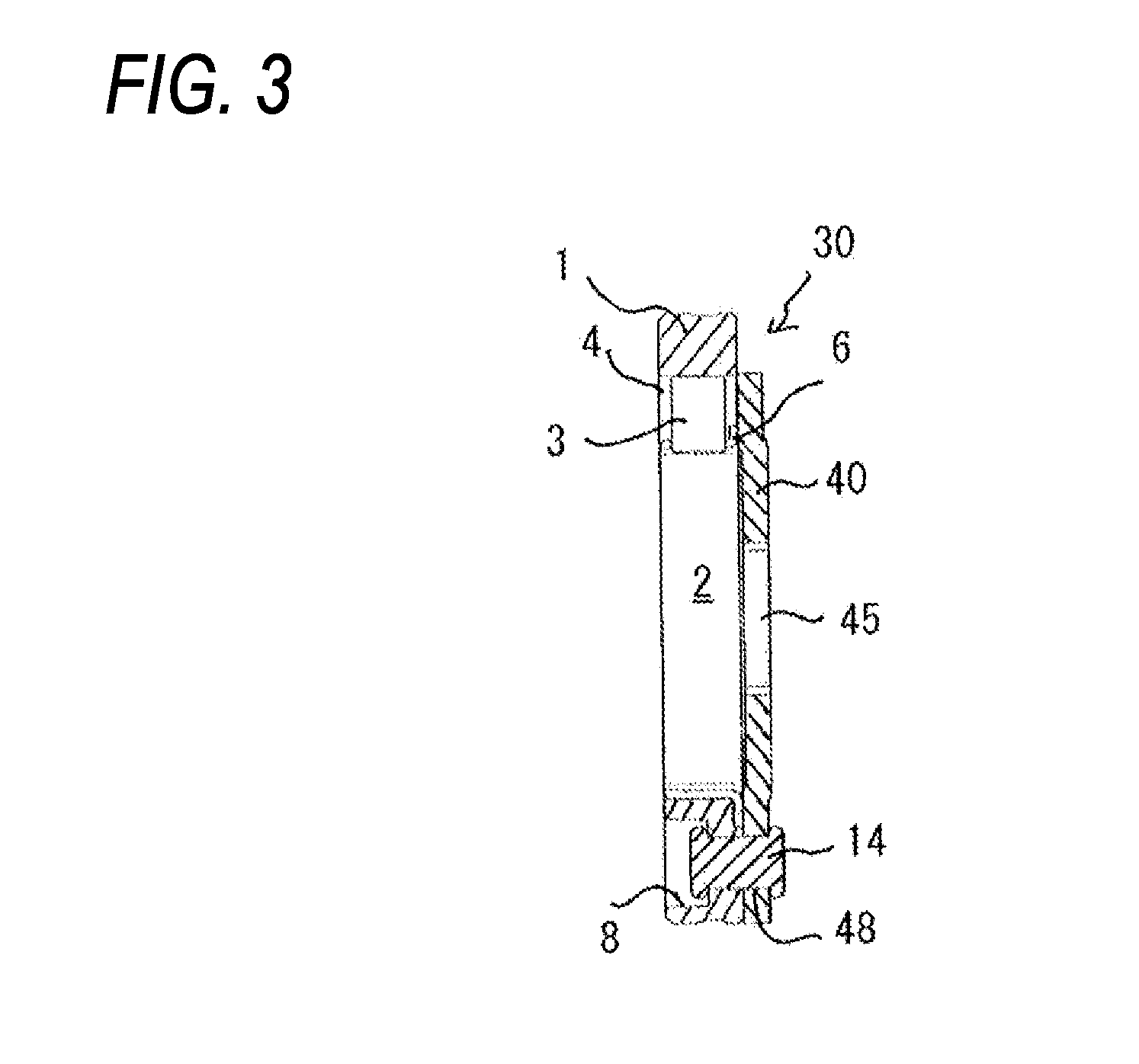
[0044]FIG. 2 is a front view illustrating a roller type one-way clutch according to a first embodiment of the present invention, and FIG. 3 is a sectional view in the axial direction taken along line III-III in FIG. 2.

[0045]As illustrated in FIG. 2, a side plate 40 of a roller type one-way clutch 30 has a non-circular (non-annular) shape, namely, a triangular shape as a whole. An end surface 21 in the axial direction of an outer race 1 is annular. At least a portion of the end surface 21 in the axial direction of the outer race 1 is exposed in a state in which the side plate 40 having a central hole 45 passing through in the axial direction is secured. The side plate 40 is provided with through holes 48 which pass through in the axial direction, in which rivets 14 penetrate, and which are positioned in the vicinity of the apexes of the triangle. The rivets 14 are inserted in the through holes 48 and holes 8 of the outer race 1 and swaged thereby to secure the side plate 40 to the ou...

second embodiment

[0048]FIG. 4 is a front view illustrating a roller type one-way clutch according to a second embodiment of the present invention, and FIG. 5 is a sectional view in the axial direction taken along line V-V in FIG. 4.

[0049]The second embodiment has the same basic configuration as that of the first embodiment. In the second embodiment, grooves 42 are formed in the surface portions substantially at the centers of three linearly trimmed portions 41 of a triangular side plate 40, the surface portions opposing pockets 4. The grooves 42 extending in the radial direction end on an inner side of the side plate 40 and open to the trimmed portions 41 at openings 43. The grooves 42 are provided one each at each of the trimmed portions 41.

[0050]As seen from FIG. 5, each of the grooves 42 ends at a position opposing the pocket 4. Thus, the pockets 4 are in communication with the outside through the grooves 42 and the openings 43. This allows foreign substances to be discharged from the pockets 4 t...

third embodiment

[0052]FIG. 6 is a front view illustrating a roller type one-way clutch according to a third embodiment of the present invention, and FIG. 7 is a sectional view in the axial direction taken along line VII-VII in FIG. 6.

[0053]In the third embodiment, a side plate 40 is cut away more than that in the first embodiment and the second embodiment. Linearly trimmed portions 41 are formed adjacently to the center of the side plate 40. In the third embodiment, therefore, pockets 4 are partly exposed on the outside diameter side of the trimmed portions 41, and cam surfaces 12 are seen.

[0054]In order to maximize the effect for discharging foreign substances, the side plate 40 is preferably disposed such that a radially outermost portion of each of the pockets 4 is exposed. The third embodiment makes it possible to further reduce the material for the side plate 40, improve the yield and discharge foreign substances from the pockets 4.


PUM


Abstract

A roller type one-way clutch includes an outer race in which at least one pocket having a cam surface on an inner periphery thereof is formed, an inner race which is spaced away from the outer race on an inside diameter side in a radial direction and which is relatively rotatably disposed concentrically with respect to the outer race, a roller which is disposed in the pocket and which engages with the cam surface to transmit a torque between the outer race and the inner race, a spring which is disposed between the outer race and the roller in the pocket and which urges the roller in a direction in which the roller engages with the cam surface, and a side plate secured to be in contact with one end surface in an axial direction of the outer race. The side plate has a non-circular shape, the one end surface in the axial direction is annular, and at least a portion of the one end surface in the axial direction of the outer race is exposed in a state in which the side plate is secured.

Description

TECHNICAL FIELD[0001]The present invention relates to a roller type one-way clutch used as a component for torque transmission, backstop or the like in a drive unit of, for example, an automobile, an industrial machine or the like, and a side plate used with a roller type one-way clutch.BACKGROUND ART[0002]In general, a roller type one-way clutch is composed primarily of an outer race in which at least one pocket having a cam surface on an inner periphery thereof is formed, an inner race which is disposed concentrically with the outer race and which has an outer peripheral track surface, a roller which is disposed in the pocket and which transmits a torque between the outer peripheral track surface of the inner race and the inner peripheral cam surface of the outer race, and a spring which is in contact with the idling side of the roller.[0003]In the roller type one-way clutch having the configuration described above, the inner race is rotated only in one direction with respect to t...

Claims


Application Information

Patent Timeline
Patent Type & Authority Applications(United States)
IPC IPC(8): F16D41/066
CPCF16D41/066F16D2041/0605F16D2041/0665F16D41/06
Inventor KURITA, TAKASHIWAKAMORI, TETSUYATOYA, RITSUO
Owner NSK WARNER
Why Eureka
Try Eureka