Touch device

a technology of touch and display panel, which is applied in the field of touch devices, can solve the problems of electrode corrosion problems, difficult to remove bubbles between the first electrode and the second electrode, and poor adhesion of conventional touch display panels, so as to avoid stress concentration and fragmentation problems, increase exhausting gaps, and improve adhesion

Active Publication Date: 2016-09-29
INNOLUX CORP
View PDF15 Cites 5 Cited by
  • Summary
  • Abstract
  • Description
  • Claims
  • Application Information

AI Technical Summary

Benefits of technology

[0008]A first right angle is formed on an edge of the first electrode, and a second right angle is formed on an edge of the second electrode. When the first electrode is connected to the second electrode, the first right angle is corresponding to a flat portion of the second electrode rather than the second right angle. The second right angle is corresponding to a flat portion of the first electrode rather than the first right angle. Therefore, while the first electrode is attached to the second electrode, the first right angle is prevented from colliding with the second right angle, and the stress concentration problem and fragmentation problem are avoided. Additionally, when the first electrode is connected to the second electrode, there are increased exhausting gaps formed between the first electrode and the second electrode in the first direction and the second direction. The bubbles between the first electrode and the second electrode can be exhausted smoothly through the exhausting gaps. The touch display panel of the embodiment of the invention has improved adhesion, and the electrode corrosion problem is prevented.

Problems solved by technology

Additionally, when the first electrodes and the second electrodes are fully connected, bubbles between the first electrodes and the second electrodes are difficult to remove.
The conventional touch display panel therefore has poor adhesion, and has electrode corrosion problems.

Method used


Image

  • Touch device
  • Touch device
  • Touch device

Examples


first embodiment

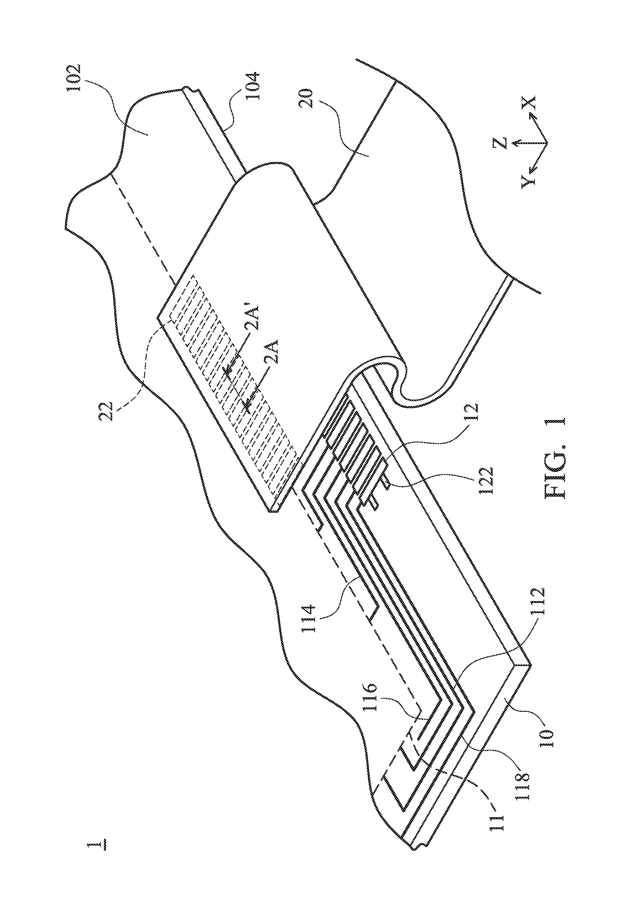
[0022]FIG. 1 shows a touch device 1 of the invention, including a first substrate 10 and a circuit board 20. The first substrate includes a touch sensing structure 11 (only schematically) and a plurality of first electrodes 12. The touch sensing structure 11 is disposed on the first substrate 10. The first electrodes 12 are electrically connected to the touch sensing structure 11. The circuit board 22 comprising a plurality of second electrodes 22 is formed thereon. The circuit board 22 can be a flexible printed circuit.

[0023]The touch sensing structure 11 of the invention can be capacitive, pressure sensitive, electromagnetic, or another touch sensing structure. The capacitive touch sensing structure can utilize mutual capacitive technology or self-capacitive technology or both self-capacitive and mutual capacitive technology. For a mutual capacitive touch sensing structure, for example, the touch sensing structure 11 includes a driving electrode and a receiving electrode (not show...

second embodiment

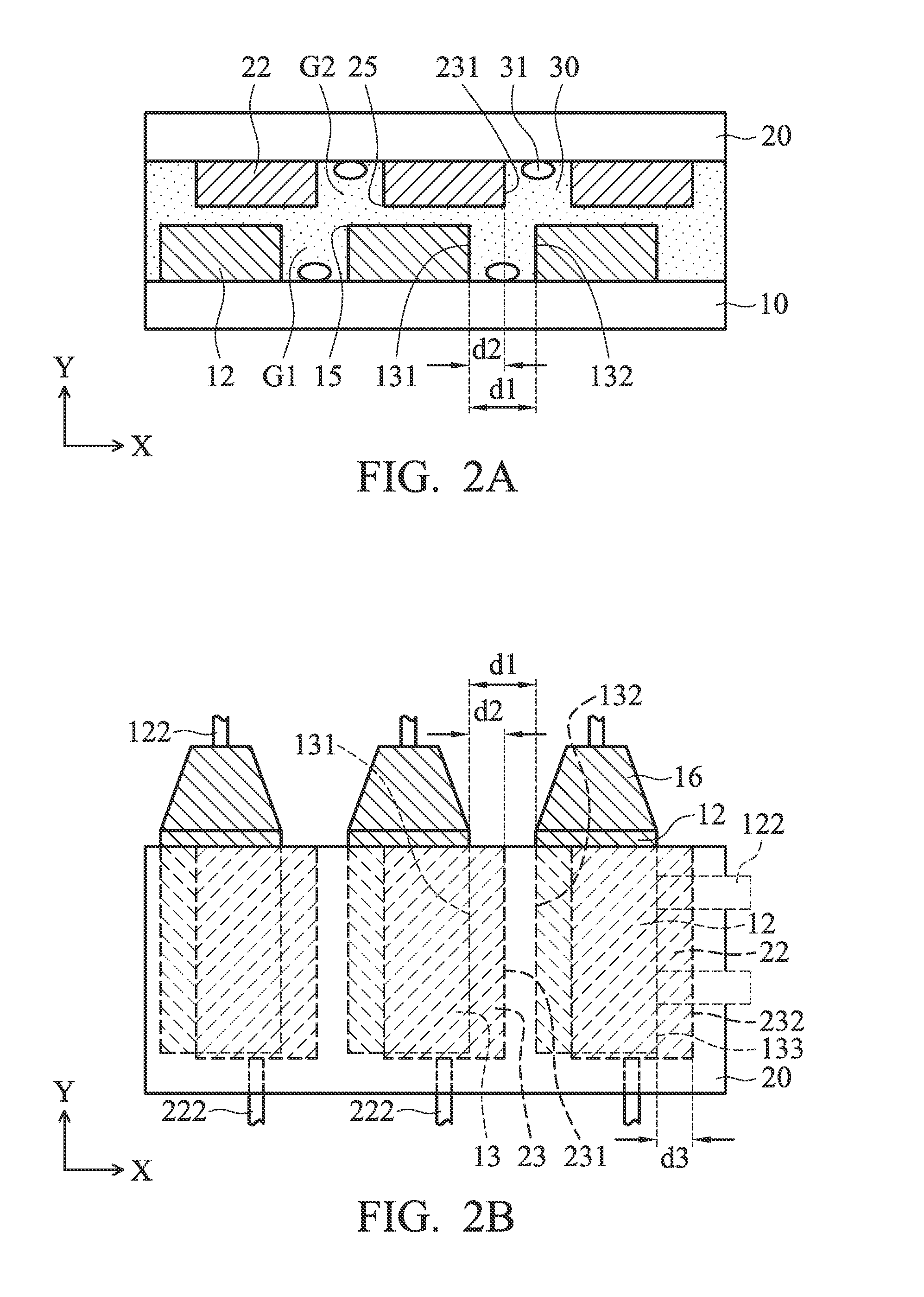
[0032]FIG. 4 shows a touch device 2 of the invention, including a first substrate 10 and touch sensing structure 20. The first substrate 10 comprises a touch sensing structure 11 and a plurality of first conductive pads 12. The touch sensing structure 11 is disposed on the first substrate 10. The first conductive pads 12 are arranged along a first direction X, wherein a space area G is formed between the two adjacent first conductive pads 12, and a minimum distance between the two adjacent first conductive pads 12 is a gap distance d1. The circuit board 20 comprises a plurality of second conductive pads 22. At least one of the second conductive pads 22 partially overlaps a space area G in a vertical projection direction of the first conductive pads 12. In other words, if we look at the second conductive pads 22 and the first substrate 10 from the vertical projection direction that is perpendicular to the second conductive pads 22, the circuit board 20 would partially overlaps the sp...


PUM


Abstract

A touch device is provided, including a first substrate and a circuit board. The first substrate includes a touch sensing structure and a plurality of first electrodes. The touch sensing structure is disposed on the first substrate. The first electrodes are arranged along a first direction. The first electrodes are disposed on the first substrate and electrically connected to the touch sensing structure, a first gap is formed between two adjacent first electrodes, and a minimum distance between the two adjacent first electrodes is a gap distance. The circuit board is partially overlapping the substrate in a vertical projection direction, the circuit board including a plurality of second electrodes corresponding to the first electrodes. One of the two adjacent first electrodes has a first electrode side edge facing the first gap. One of the second electrodes has a second electrode side edge located in the first gap.

Description

CROSS REFERENCE TO RELATED APPLICATIONS[0001]This Application claims priority of Taiwan Patent Application No. 104109150, filed on Mar. 23, 2015, the entirety of which is incorporated by reference herein.BACKGROUND OF THE INVENTION[0002]1. Field of the Invention[0003]The present invention relates to a touch device, and in particular to an electrode design of the touch device.[0004]2. Description of the Related Art[0005]First electrodes of a bonding area of a conventional touch display panel are utilized to be electrically connected to second electrodes on a flexible circuit board aligned in a specific direction. Conventionally, the first electrodes are fully corresponding to the second electrodes. A first right angle is formed on an edge of the first electrode, and a second right angle is formed on an edge of the second electrode. When the first and second electrodes are fully connected to each other, the first right angle collides with the second right angle, and the first and seco...

Claims


Application Information

Patent Timeline
Patent Type & Authority Applications(United States)
IPC IPC(8): G06F3/044
CPCG06F3/044G06F3/0446G06F3/0445G06F3/04164
Inventor CHANG, CHIA-HSIUNGCHEN, YANG-CHENSU, KUO-CHANGCHU, HSIA-CHING
Owner INNOLUX CORP
Why Eureka
Try Eureka