
Printer monitoring

Active Publication Date: 2016-09-29
INTEL CORP
View PDF4 Cites 37 Cited by
  • Summary
  • Abstract
  • Description
  • Claims
  • Application Information

AI Technical Summary

Benefits of technology

The present patent is about monitoring a 3D printer during a print job to detect and address any problems that might arise. The monitoring system includes a camera and computer vision techniques to analyze images captured by the camera and compare them to a baseline image to determine if the print job is progressing as expected. The system can alert the operator when there is a problem, allowing them to fix it quickly. The monitoring system can save time and money by alerting the operator and allowing them to leave the premises and come back to correct any issues. Overall, the monitoring system helps ensure that print errors are caught and addressed in a timely manner.

Problems solved by technology

3D printing of an object can take a long time to complete.
Several failure modes can and frequently do occur, including de-adhesion to the build platform, non-optimal printer parameters resulting in a mal-formed object, and running out of plastic, to name a few.
Many hours of printing time can be wasted if the print error is not discovered in a timely manner, which may result in delays in completing a project.

Method used


Image

  • Printer monitoring
  • Printer monitoring
  • Printer monitoring

Examples


example 2

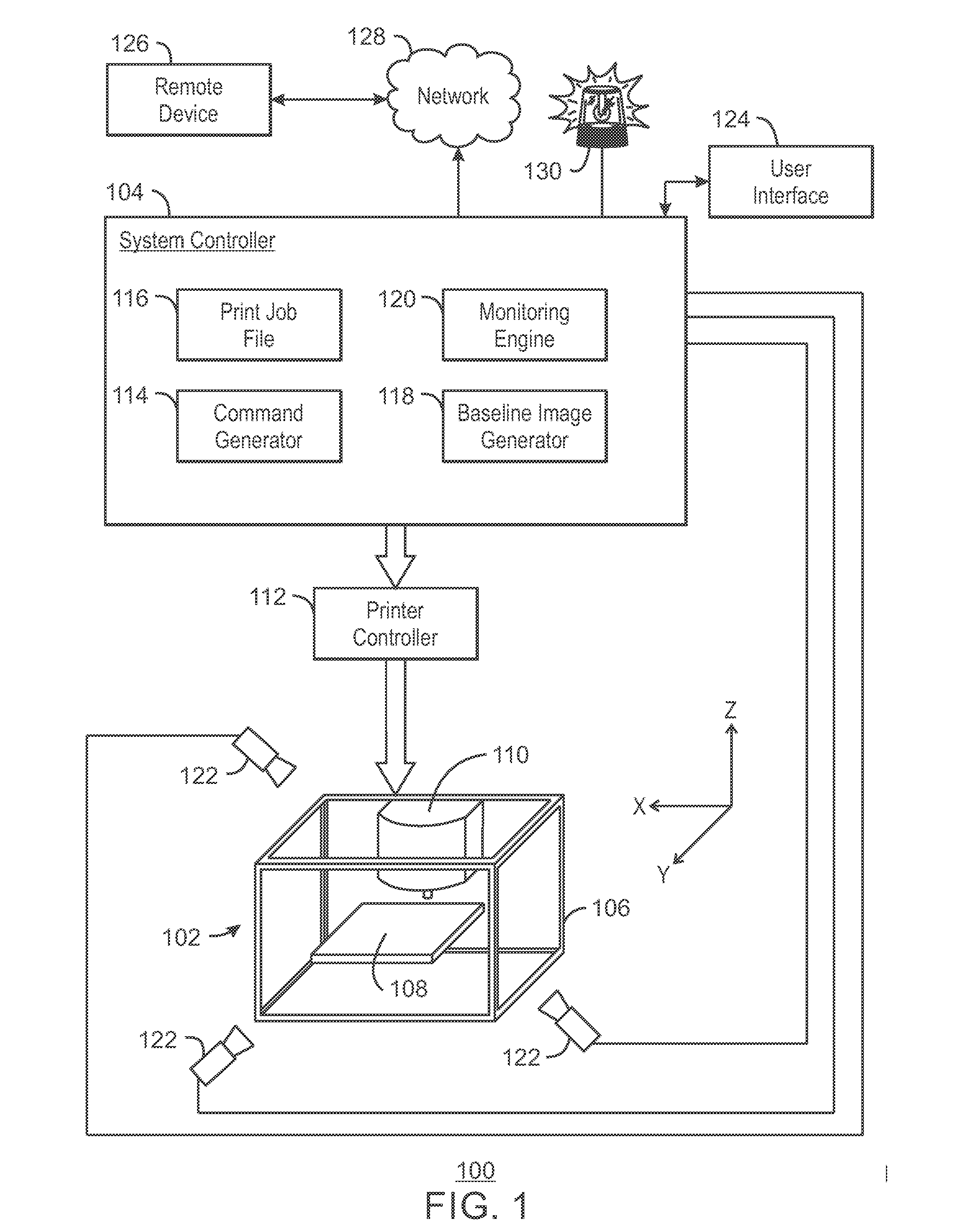
[0055 includes the system of example 1. In example 2, the baseline image generator generates the model from print commands used to drive the 3D printer. Optionally, the print commands are in G-code format.

example 3

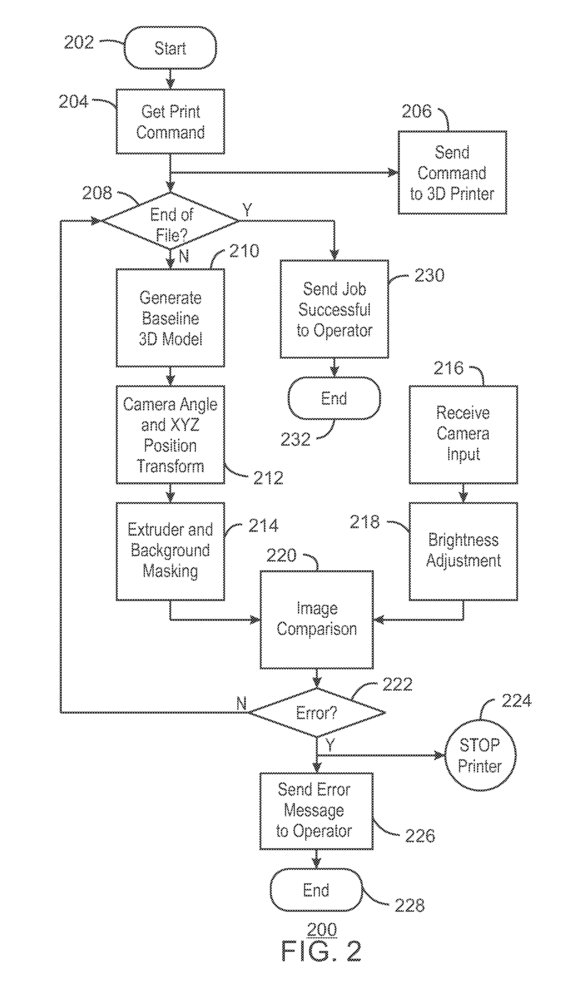
[0056 includes the system of any combination of examples 1-2. In example 3, to generate the baseline image, the baseline image generator is to transform the 3D model to match the perspective of the camera.

example 4

[0057 includes the system of any combination of examples 1-3. In example 4, to generate the baseline image, the baseline image generator is to perform a rotational transformation of the 3D model based on a position of the camera relative a build platform of the 3D printer.


PUM


Abstract

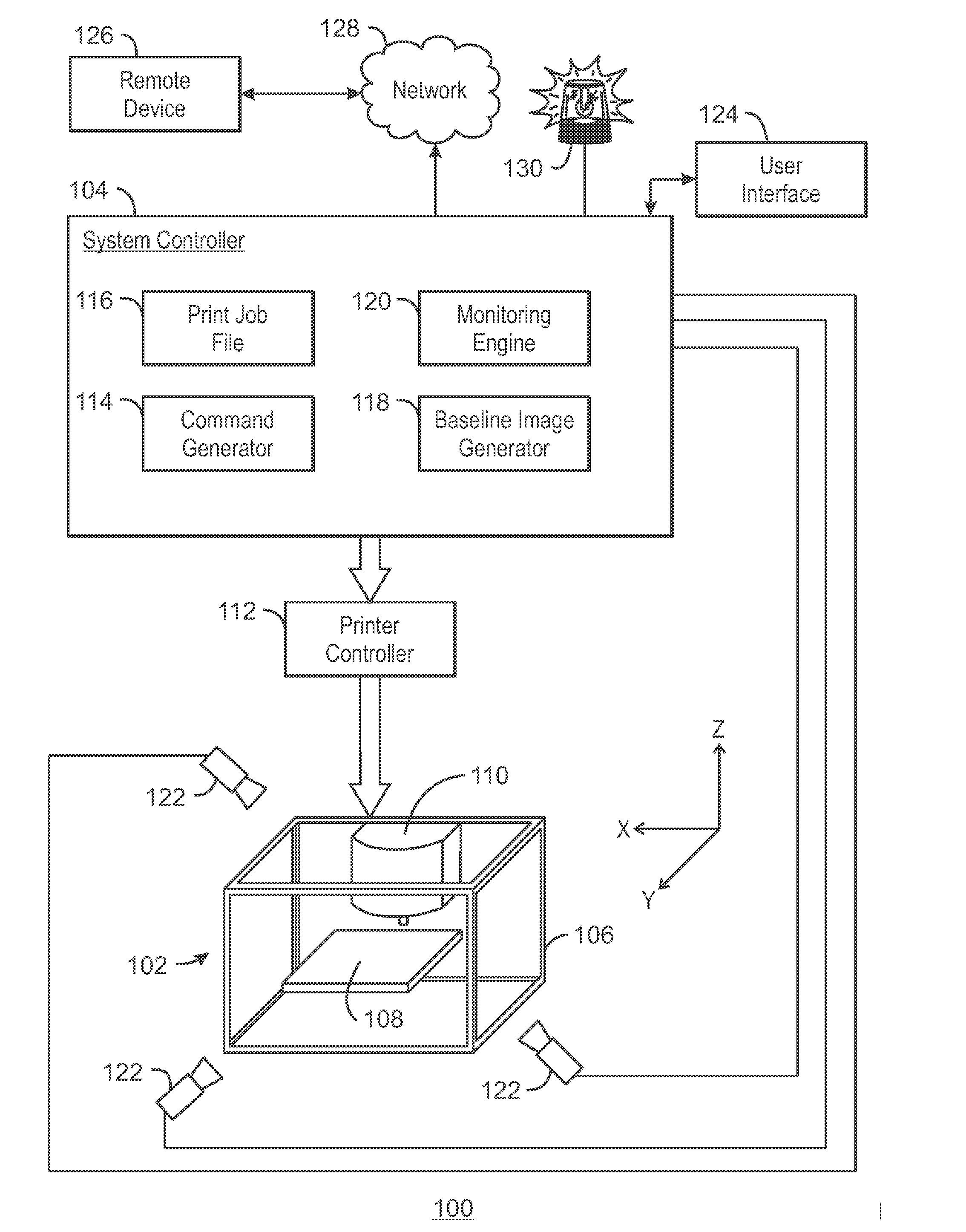
Techniques for monitoring a three-dimensional (3D) printer during the performance of a print job are described herein. An example of a system in accordance with the present techniques includes a camera to generate an image of a 3D print job in progress. The system also includes a baseline image generator to generate a baseline image based on a 3D model of the object to be printed. The system also includes a monitoring engine to compare the image with the baseline image to determine a status of the 3D print job and trigger an alarm if the 3D print job fails.

Description

TECHNICAL FIELD[0001]The present disclosure relates generally to techniques for electronically monitoring a printing system. More specifically, the present disclosure describes techniques for monitoring a three-dimensional (3D) printer during a print job.BACKGROUND ART[0002]3D printing of an object can take a long time to complete. Several hours is not uncommon, depending on the size and complexity of the object. Several failure modes can and frequently do occur, including de-adhesion to the build platform, non-optimal printer parameters resulting in a mal-formed object, and running out of plastic, to name a few. Many hours of printing time can be wasted if the print error is not discovered in a timely manner, which may result in delays in completing a project.BRIEF DESCRIPTION OF THE DRAWINGS[0003]FIG. 1 is a block diagram of a system for monitoring a 3D printer during the performance of a print job.[0004]FIG. 2 is a process flow diagram of a method of monitoring a 3D printer durin...

Claims


Application Information

Patent Timeline
IPC IPC(8): G06K15/00G06K15/02
CPCG06K15/021G06K15/408B41J29/393H04N1/32609B33Y10/00B33Y50/02B29C64/386H04N1/46H04N1/00925H04N1/00042H04N1/00034H04N1/00074H04N1/00015H04N1/00045H04N1/00087G06V2201/12B33Y99/00
Inventor PEEK, GREGORY A.
Owner INTEL CORP
Learn More