Wiring harness protector fixing structure

a technology for fixing structures and wiring harnesses, which is applied in the direction of insulated conductors, cable connections, coupling devices, etc., can solve the problems of affecting the protection of the targeted part, the protector is displaced the difficulty of positioning the protector on the wiring harness, etc., to achieve excellent durability, improve waterproofness, and improve waterproofness

Active Publication Date: 2016-09-29
SUMITOMO WIRING SYST LTD
View PDF1 Cites 5 Cited by
  • Summary
  • Abstract
  • Description
  • Claims
  • Application Information

AI Technical Summary

Benefits of technology

[0020]According to the seventh aspect, since a rib or the like is not provided on the outer surface of the tubular portion of the metal bracket and a groove or the like needs not be provided also on the inner surface of the protecting tube portion of the protector covering the tubular portion unlike before, the seal rubber can be mounted on the tubular portion. This enables the clearance between the tubular portion and the protecting tube portion to be closed and waterproofness to be improved.
[0021]In the present invention, the engaging projections are provided on the flange portion extending from the tubular portion of the metal bracket, whereas the engaging holes are provided on the flange wall portions of the wiring harness protector, and the protector is fixed to the metal bracket by engaging the engaging projections and the engaging holes. Thus, as compared to a conventional case provided with a fixing structure by a rib and a groove between the outer surface of a tubular portion of a metal bracket and the inner surface of a protecting tube portion of a protector, a problem of penetration of water outside into the protector via the fixing structure can be prevented and a measure for improving waterproofness by mounting a rubber seal on the tubular portion to close a clearance between the tubular portion and the protecting tube portion if necessary can be adopted. Further, since the wiring harness protector is configured by the first and second divided bodies, the operation of arranging the protecting tube portion of the wiring harness protector around the tubular portion of the metal bracket and the operation of engaging the engaging projections and the engaging holes constituting the fixing structure can be easily performed. In addition, since the contact surfaces of the flange wall portions provided on the wiring harness protector are configured to come into contact with the flange portion of the metal bracket, a tensile force of the wiring harness and the like can be supported between the flange portion of the metal bracket and the wide contact surfaces of the flange wall portions of the protector. Therefore, the wiring harness protector can be firmly positioned and fixed to the end part of the wiring harness with excellent durability.

Problems solved by technology

However, if a suitable mounting member such as a vehicle body panel is not present near an arrangement position of the protector, it is difficult to position the protector on the wiring harness.
Thus, there has been a problem that the protector is displaced on the wiring harness and cannot protect a targeted part if the protector is merely externally fitted to the wiring harness.
However, if the engaging groove for accommodating the locking rib of the metal bracket is provided on the inner surface of the protector, there is a possibility that water enters inside through a small clearance between the locking rib and the engaging groove when an outer surface of the protector is exposed to water.
Further, if a tensile force of the wiring harness is applied between fitting surfaces of the thin locking rib and the thin engaging groove in a concentrated manner there is a possibility that breakage of an accommodation groove or the like can occur.
In such cases, the locking rib formed on the tubular portion obstructs the mounting of the rubber seal, wherefore there is also an inherent problem of being difficult to adopt a fixing structure using the locking rib.

Method used


Image

  • Wiring harness protector fixing structure
  • Wiring harness protector fixing structure
  • Wiring harness protector fixing structure

Examples


Embodiment Construction

[0030]Hereinafter, an embodiment of the present invention is described with reference to the drawings.

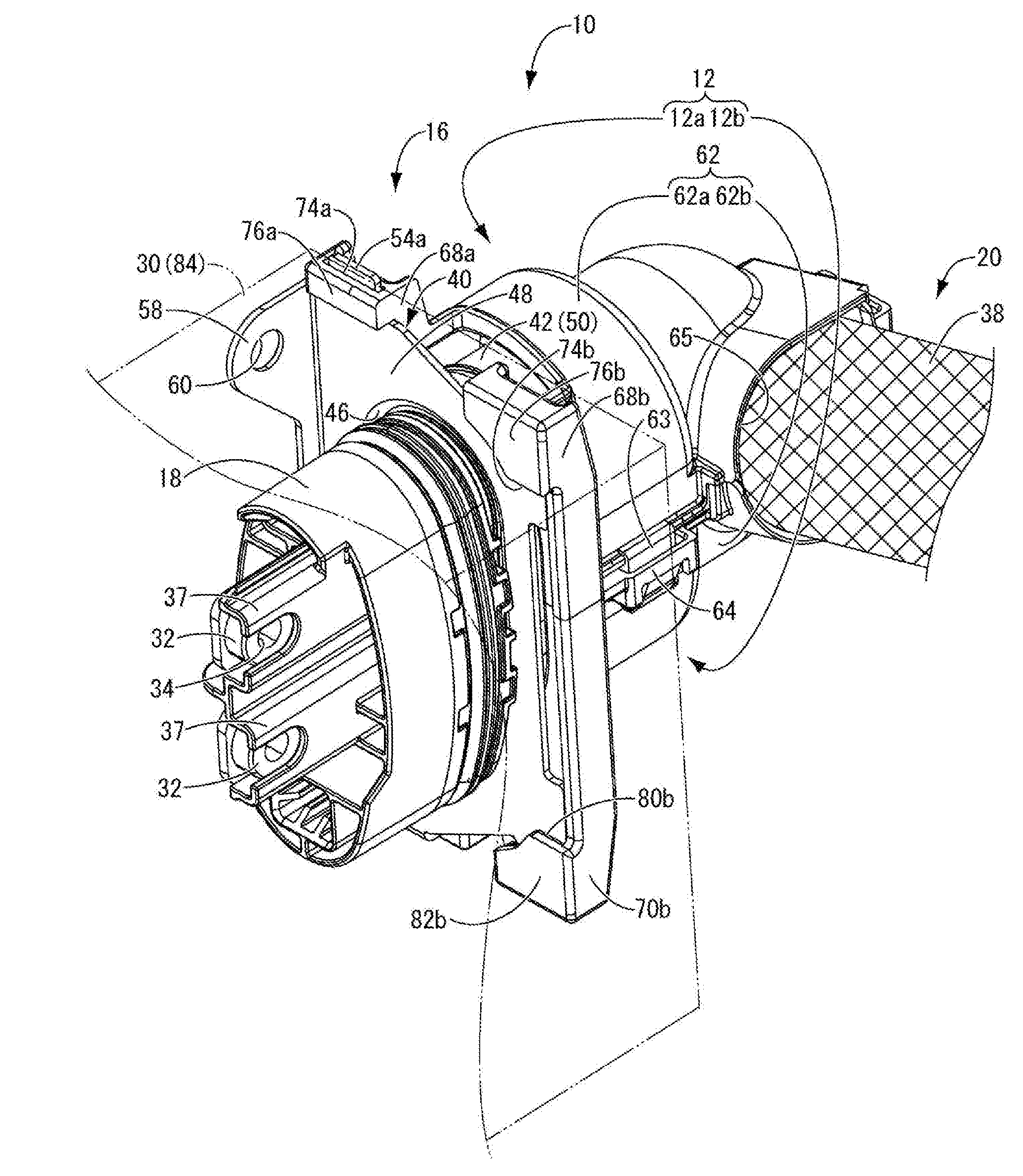
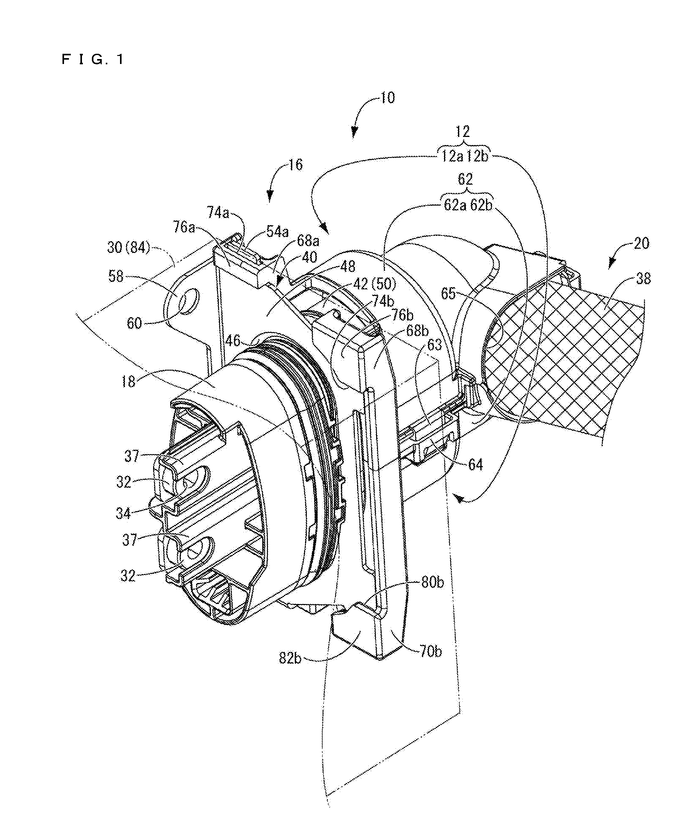
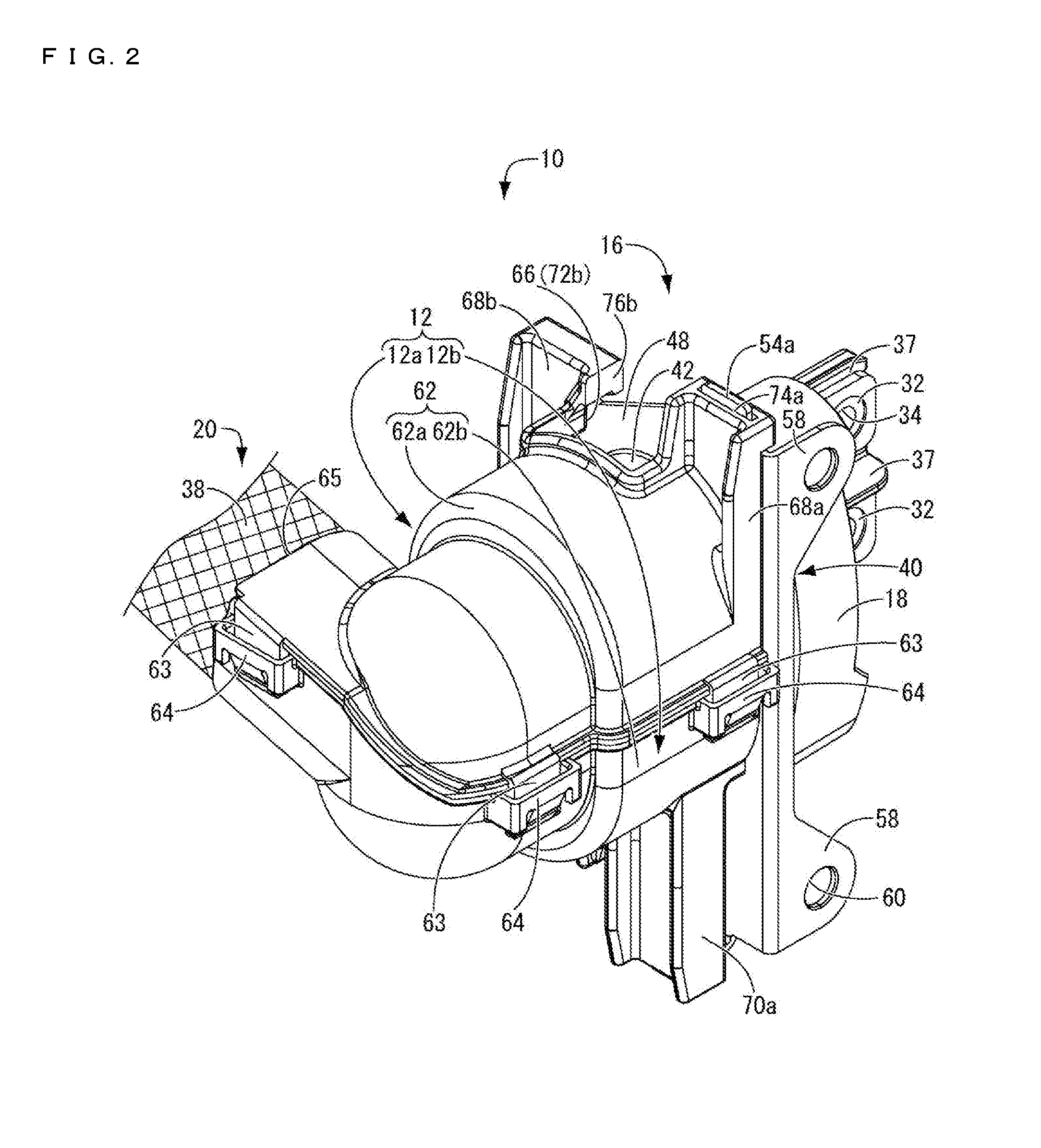
[0031]FIGS. 1 to 8 show a wiring harness 10 and a wiring harness protector 12 provided with a wiring harness protector fixing structure as one embodiment of the present invention. Note that fixing portions 58 to be described later are located on an upper side and a braided wire 38 is located on a lower side in a vehicle mounted state.

[0032]As shown in FIG. 1, the wiring harness 10 is used, for example, to connect electrical devices such as an inverter and a motor in an electric vehicle. The wiring harness 10 is structured such that a connector housing 18 is provided on end parts 16 of a plurality of wires 14 and a shield member 20 is externally fitted to the connector housing 18 and wires 14. In this embodiment, the plurality of wires 14 comprises two wires. As shown in FIG. 4, the wire 14 includes a core 22 formed by bundling a plurality of metal wires made of copper, aluminum or t...


PUM

PropertyMeasurementUnit
tensile forceaaaaaaaaaa
durabilityaaaaaaaaaa
external forceaaaaaaaaaa

Abstract

It is aimed to provide a wiring harness protector fixing structure having a novel structure and capable of firmly positioning and fixing a protector to an end part of a wiring harness with excellent durability while improving waterproofness even if a mounting member such as a vehicle body panel is not present around. Engaging projections are formed on a flange portion of a metal bracket, whereas a wiring harness protector includes a first divided body and a second divided body to be assembled and integrated. By assembling the first and second divided bodies, the engaging projections of the metal bracket are engaged with engaging holes provided on flange wall portions of the first and second divided bodies, and contact surfaces and provided on at least parts of the flange wall portions come into contact with the flange portion of the metal bracket.

Description

BACKGROUND[0001]1. Field of the Invention[0002]The present invention relates to a wiring harness protector fixing structure to be mounted on an end part of a wiring harness to which a shield member made of metal and fixed to another member is externally fitted.[0003]2. Description of the Related Art[0004]Electric devices such as an inverter and a motor of an automotive vehicle are connected by a wiring harness, for example, in an electric vehicle, a hybrid vehicle or the like. As described in Japanese Unexamined Patent Publication No. 2004-178913, a metal bracket, including a tubular portion into which the wiring harness is inserted, and a shield member formed of a braided wire extending from an end part of the tubular portion are externally fitted to the wiring harness to provide a shield function and prevent the leakage of electrical noise generated from an inverter and the like to outside through the wiring harness. An end part of the metal bracket is fixed to another member, suc...

Claims


Application Information

Patent Timeline
Patent Type & Authority Applications(United States)
IPC IPC(8): H01B7/17B60R16/02H01B7/00
CPCH01B7/17B60R16/0215H01B7/0045H01R13/502H01R13/5202H01R13/5841H01R2201/26B60R16/0222H02G3/0462H02G3/04H02G3/34
Inventor SUZUKI, TAKASHI
Owner SUMITOMO WIRING SYST LTD
Why Eureka
Try Eureka