
Battery pack and heater assembly

a battery pack and heater technology, applied in the direction of battery/fuel cell control arrangement, cell components, battery/cylinder output, etc., can solve the problems of reducing recharging capacity, non-uniform charge-discharge behavior among the batteries, and reducing the output of the battery pack, so as to suppress the variation in temperature among the heated cylindrical batteries in the battery pack. , to achieve the effect of suppressing the variation in temperature among the heated cylindrical batteries

Active Publication Date: 2016-09-29
TOYOTA JIDOSHA KK
View PDF2 Cites 11 Cited by
  • Summary
  • Abstract
  • Description
  • Claims
  • Application Information

AI Technical Summary

Benefits of technology

The patent text describes a configuration for heating batteries in a battery pack to prevent temperature variations and ensure even heating. The configuration involves heating the air in the vicinity of a thermal diffusing plate, which then heats the plurality of cylindrical batteries through convection. This prevents localized heating and ensures uniform temperature among the heated batteries. Additionally, the bottom cover of the battery pack is heated to suppress temperature variations in the air space below. Overall, this configuration promotes compactness and efficient use of the battery pack space.

Problems solved by technology

Such battery packs cause problems, such as decrease in output thereof and decrease in recharging capacity, if the temperature thereof becomes lower.
In a battery set including a plurality of batteries connected in series or in parallel, a difference in temperature among the batteries might cause non uniform charge-discharge behavior among the batteries.
Therefore, particular batteries experience significant decrease in residual capacity, which might cause progress of deterioration to the particular batteries.
Unfortunately, as in the case of the technique described in JP 5392407 B, if the heater is directly disposed to the battery holder, the portion of the battery holder in contact with the heater is locally heated, thus causing a difference in temperature among the batteries heated through the battery holder, which results in variation in temperature among the heated batteries.
As in the case of the technique described in JP 2012-243535 A, in a method of bringing a heating surface of each heating element to be in contact with part of the outer circumference of each cylindrical battery, there occurs difference in temperature between part of each battery in contact with the heating surface and part of this battery out of contact with the heating surface, thus causing difference in inner temperature of the same battery, which might result in variation in temperature among the heated batteries.
In addition, in the technique described in JP 2008-053149 A, since a gap cannot be provided below each mounting portion that supports the stacked batteries in the casing, this mounting portion cannot be heated by the heater, which might cause variation in temperature among the heated stacked batteries.

Method used


Image

  • Battery pack and heater assembly
  • Battery pack and heater assembly
  • Battery pack and heater assembly

Examples


Embodiment Construction

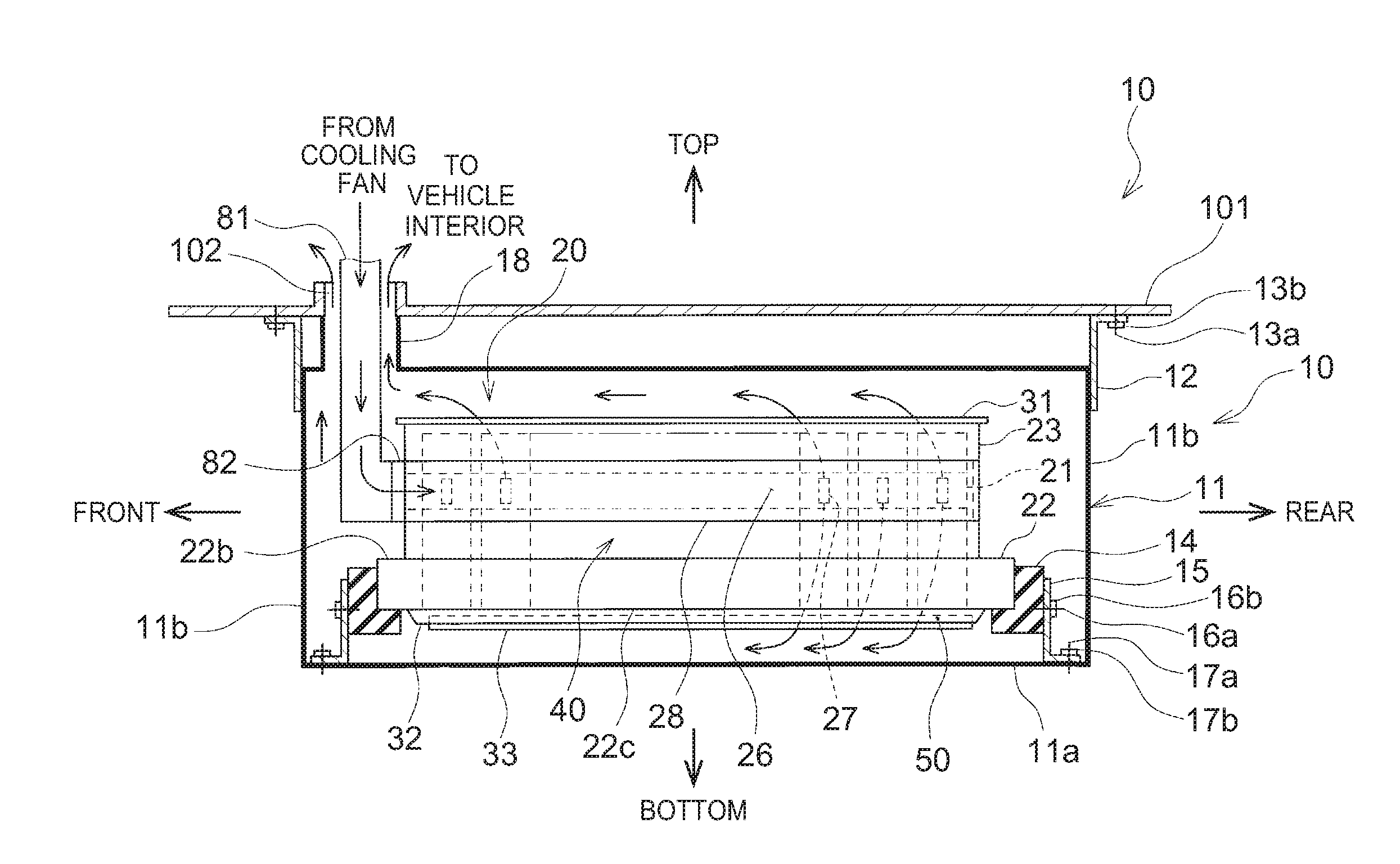
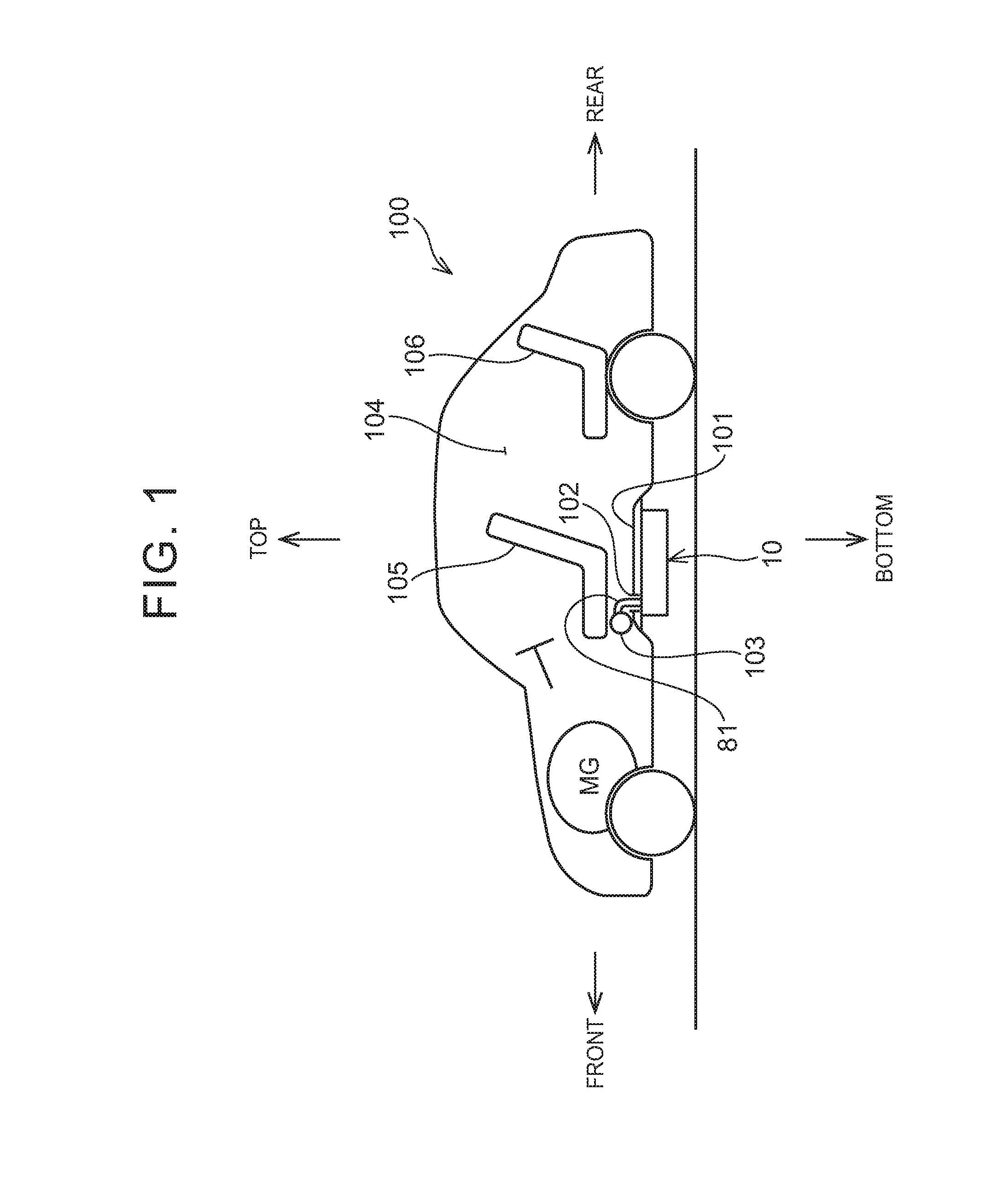
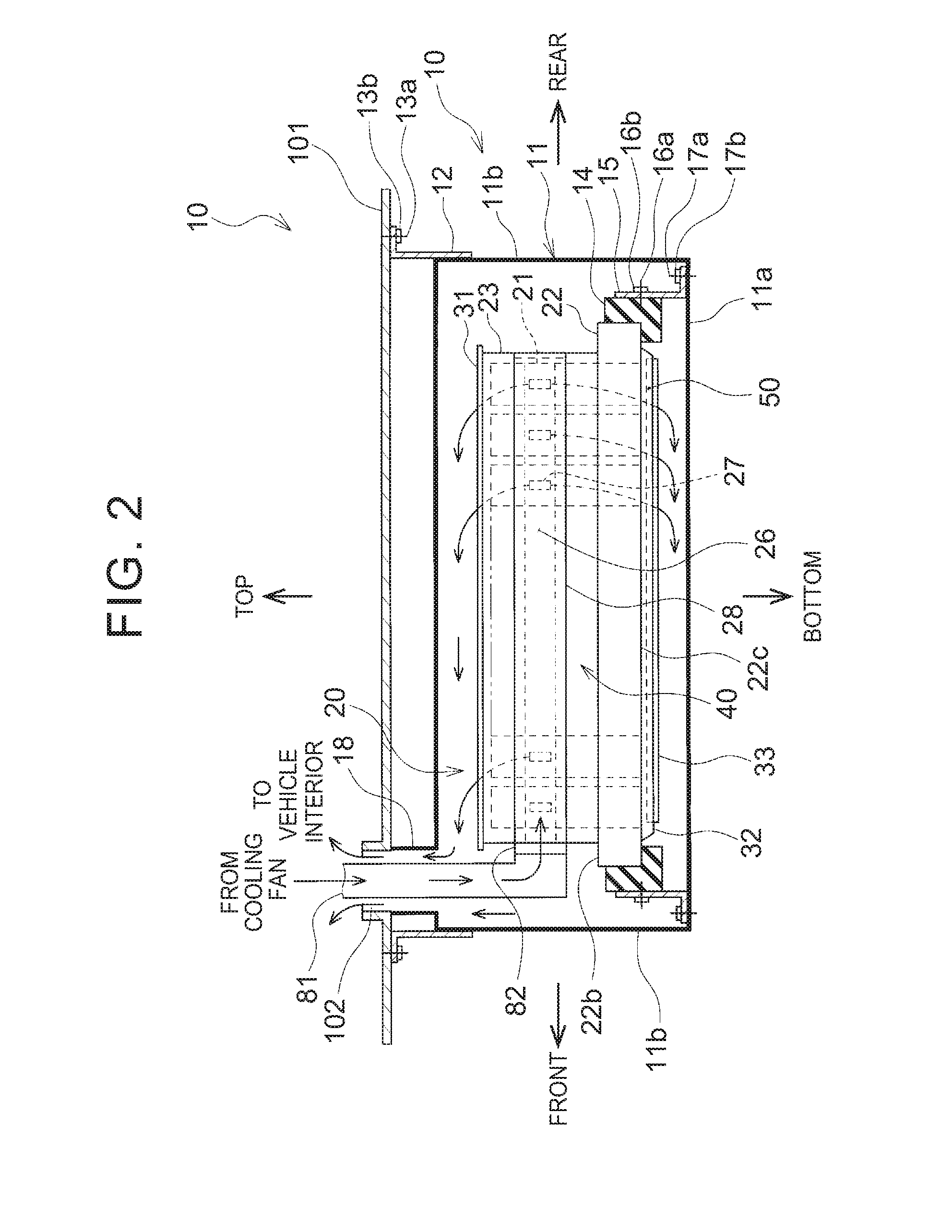
[0032]Hereinafter, a first embodiment of the disclosure will be described with reference to drawings. In the following first embodiment, a battery pack of an electric-motor vehicle 100 driven by a motor generator will be explained. The battery pack 10 is disposed adjacent to a bottom surface of a floor panel 101 in the vicinity of a front seat 105, as shown in FIG. 1. More specifically, as shown in FIG. 2, a casing 11 is fixed to a bottom surface of the floor panel 101 of the electric-motor vehicle 100 with brackets 12 attached to side plates 11b, bolts 13a, and nuts 13b. This means that the casing 11 is hung from the floor panel 101. Cooling air to cool batteries housed in the battery pack 10 is supplied by a cooling fan 103 disposed inside a vehicle interior 104. In FIG. 1, “TOP” denotes a vertically upward direction. Similarly, in FIG. 1, “BOTTOM” denotes a vertically downward direction, “FRONT” denotes a frontward direction of the electric-motor vehicle 100, and “REAR” denotes a...


PUM


Abstract

A battery pack including a battery module and a heater is provided. The battery module includes a plurality of cylindrical batteries, a thermal diffusing plate, a first chamber, and a second chamber. The thermal diffusing plate houses and holds the plurality of cylindrical batteries. The first chamber is configured to distribute cooling air to cool each of the plurality of cylindrical batteries. The second chamber is formed at least in part by the thermal diffusing plate. The heater is configured such that convection occurs in the second chamber.

Description

CROSS-REFERENCE TO RELATED APPLICATIONS[0001]This application claims priority from Japanese Patent Application No. 2015-059201, filed in the Japanese Patent Office on Mar. 23, 2015, the disclosure of which, including the specification, drawings and abstract, is incorporated herein by reference in its entirety.BACKGROUND[0002]1. Field[0003]The disclosure relates to a structure of a battery pack including a battery module containing a plurality of cylindrical batteries.[0004]2. Description of Related Art[0005]Battery packs configured by housing battery sets including a number of batteries connected in series or in parallel in casings are used in electric-motor vehicles or the like. Such battery packs cause problems, such as decrease in output thereof and decrease in recharging capacity, if the temperature thereof becomes lower. To cope with this, there has been a proposal to provide a battery pack with a heater so as to heat each battery by this heater if the temperature thereof is lo...

Claims


Application Information

Patent Timeline
IPC IPC(8): H01M10/615H01M2/10H01M10/625H01M10/663H01M10/613H01M10/6554H01M10/6562B60L50/64
CPCH01M10/615H01M10/6554H01M2/1077H01M2220/20H01M10/663H01M10/613H01M10/625H01M10/6562H01M10/6555H01M50/271B60L50/64H01M50/249H01M50/213H01M10/657H01M10/643H01M10/6561B60L2240/545B60L58/27B60L50/66Y02T10/70Y02E60/10H01M10/60
Inventor KIMURA, KENJI
Owner TOYOTA JIDOSHA KK
Learn More