High-power microwave tube with beam spreading in the collector

a high-power microwave tube and collector technology, applied in the field of high-power microwave tubes, to achieve the effect of reducing costs and simplifying devices

Inactive Publication Date: 2010-07-06
THALES SA
View PDF11 Cites 5 Cited by
  • Summary
  • Abstract
  • Description
  • Claims
  • Application Information

AI Technical Summary

Benefits of technology

[0022]A principal object of the invention is to even out the variation in temperature on the collector of microwave power tubes. To this end, the amplitude modulation of the signal ensures a variation in time of the cusp position of the beam in the collector.
[0023]Another object of this invention is the possibility of simplifying the device for cooling power tubes and therefore reducing the cost.

Problems solved by technology

This cooling can be obtained generally by circulation of water using a large and cumbersome cooling installation.

Method used


Image

  • High-power microwave tube with beam spreading in the collector
  • High-power microwave tube with beam spreading in the collector
  • High-power microwave tube with beam spreading in the collector

Examples


Embodiment Construction

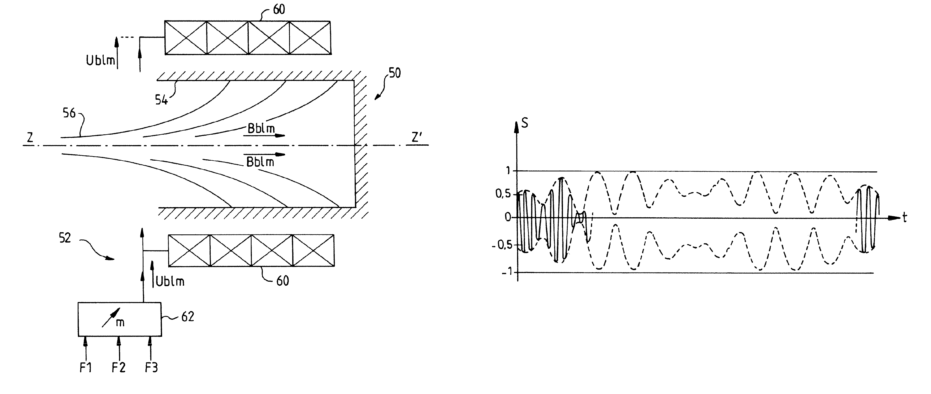
[0038]FIG. 6a gives a view of a collector 50 of an embodiment of a gyrotron according to the invention comprising a device 52 for spreading the beam.

[0039]The collector 50 comprises a conductive wall 54, which is cylindrical along the axis ZZ′ of the tube, for receiving the electrons. A beam 56 of electrons exiting the microwave structure of the tube in particular strikes the conductive inner wall 54 of the collector.

[0040]The spreading device comprises a coil 60, with revolution axis ZZ′, surrounding the conductive wall 54 of the collector. The coil 60, which is fed with a spread signal Ublm, generates a magnetic spread field Bblm, which is periodic and amplitude-modulated, along the axis ZZ′ of the collector 50.

[0041]The spread signal Ublm will be given by the signal S which is normalized at an amplitude equal to 1, where Ublm=k.S, k being an amplification factor required to drive the coil 60.

[0042]S=(1+m·sin⁢⁢ω3⁢t·sin⁢⁢ω2⁢t)1+m·sin⁢⁢ω1⁢t

m being the modulation parameter, with its ...


PUM


Abstract

The invention relates to a microwave power tube consisting of an electron gun comprising a cathode that generates an electron beam in a microwave structure of the tube, and a collector for collecting electrons from the beam. In addition, the tube comprises a magnetic device for spreading the beam in the collector, which generates a periodic amplitude-modulated magnetic spread field Bblm. The invention is suitable for microwave power tubes.

Description

CROSS-REFERENCE TO RELATED APPLICATIONS[0001]The present Application is based on International Application No. PCT / EP2005 / 055563 filed on Oct. 26, 2005, which in turn corresponds to France Application No. 04 11447 filed on Oct. 27, 2004, and priority is hereby claimed under 35 USC §119 based on these applications. Each of these applications are hereby incorporated by reference in their entirety into the present application.FIELD OF THE INVENTION[0002]The invention relates to high-power microwave tubes and notably the electron collector of the tube.[0003]This invention can be used in klystron-type and gyrotron-type tubes, and traveling wave tubes, etc.BACKGROUND OF THE INVENTION[0004]High-power microwave tubes provide electromagnetic energy from the kinetic energy of the electrons emitted by a diode (electron gun) of the tube. The electrons from the beam are finally collected at one end of the tube by an electron collector.[0005]FIG. 1 shows the trajectories Tj of the electrons of a ...

Claims


Application Information

Patent Timeline
Patent Type & Authority Patents(United States)
IPC IPC(8): H01J23/16H01J25/10
CPCH01J23/027H01J23/033H01J25/02
Inventor BARIOU, DAVIDLIEVIN, CHRISTOPHE
Owner THALES SA
Why Eureka
Try Eureka