Spacecraft

a technology for spacecraft and planetary satellites, applied in the field of spacecraft, can solve the problems of limited effectiveness of heaters, long validation tests, and fluctuation of the temperature of satellite faces, and achieve the effect of less costly manufacturing

Active Publication Date: 2017-11-28
AIRBUS DEFENCE & SPACE
View PDF9 Cites 5 Cited by
  • Summary
  • Abstract
  • Description
  • Claims
  • Application Information

AI Technical Summary

Benefits of technology

[0013]The purpose of the present invention is to propose a system that has a lower cost, is more reliable, and would allow the variations in temperature between the North and South faces of a satellite during the equinoxes and during the solstices to be limited.
[0020]Advantageously, in the present invention, the slats are stationary with respect to the supporting arm. This results in a system that is simpler, less costly and more reliable.
[0021]Advantageously, the assembly according to the invention has a surface containing holes that variably and selectively (1% to 100%) absorbs the incident solar radiation. Indeed, the solar radiation “passes through” the assembly during the solstices. This gives it the quality of being discrete during the desired season and allows its “stationary” nature.
[0024]Advantageously, the assembly according to the invention is less costly to manufacture. Moreover, it is passive and does not require an electric power supply.

Problems solved by technology

Moreover, the temperature of the faces of the satellite also fluctuates over time.
These validation tests are long and complex to carry out.
Nevertheless, the heaters have limited effectiveness and require the electric power system of the satellite to be oversized.
This oversizing notably increases the cost of the satellite.
Moreover, these louvers require a complex mechanism allowing the rotation of the louvers.
This device, however, requires one or two additional electric motors.
This or these motors make the satellite heavier and increase its manufacturing cost.
Moreover, the satellite of document JP H03 109999 is not secure.
If a part or one of the motors for rotating the heat-radiating plates breaks down during a mission, it is difficult to repair them.
If, in addition, this breakdown takes place during the solstices, the heat-radiating plates remain in a position that will increase the temperature differences during the other seasons and will endanger the operation of the on-board electronic equipment.

Method used


Image

  • Spacecraft
  • Spacecraft
  • Spacecraft

Examples


Embodiment Construction

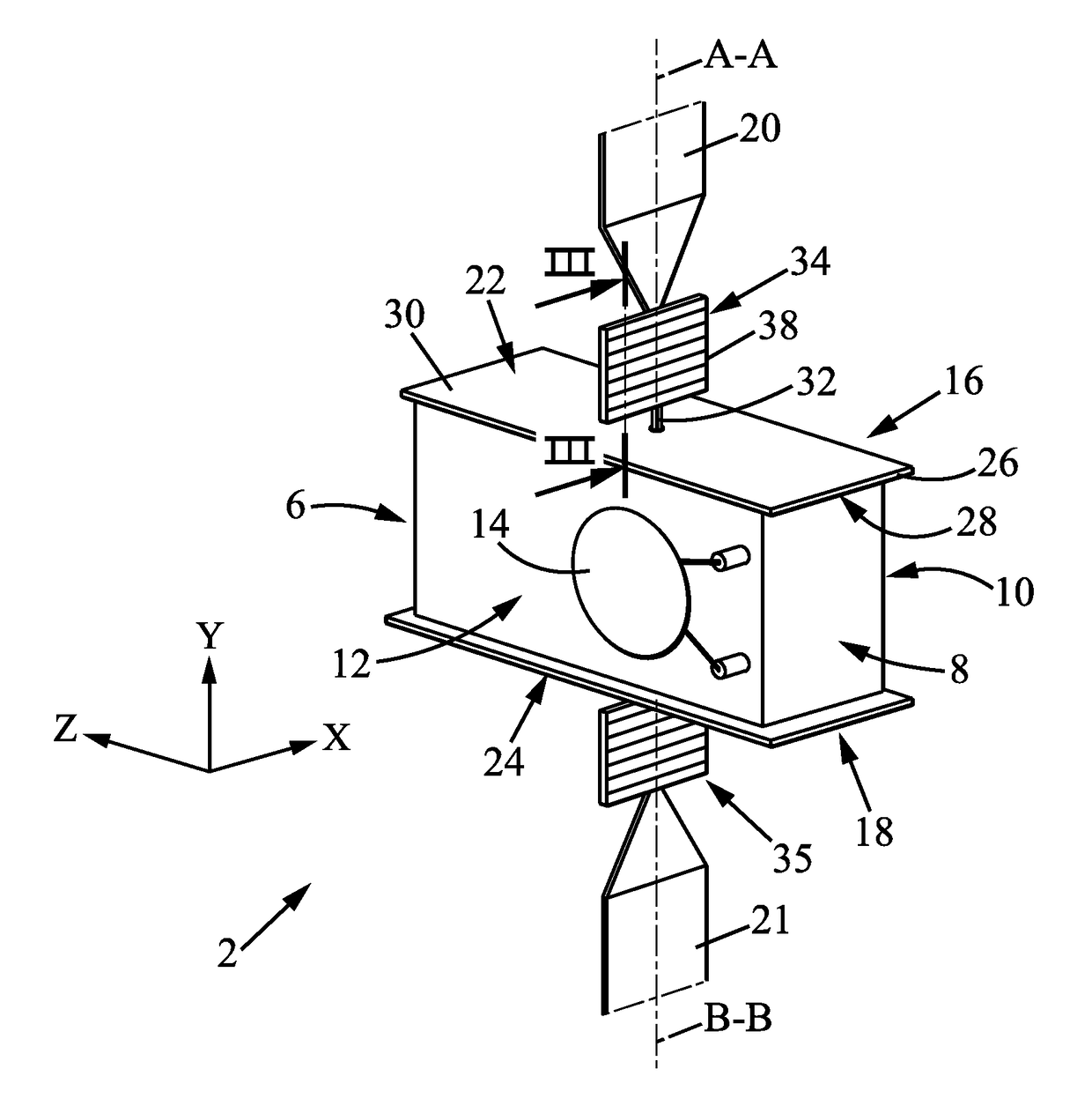
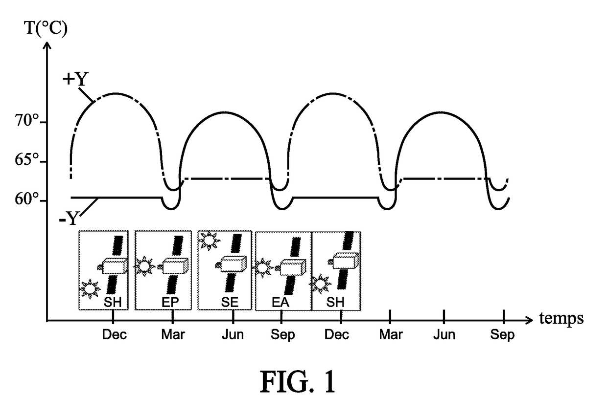
[0047]The present invention is defined with respect to an orthogonal reference frame R (X, Y, Z) shown in FIGS. 2 to 5. The direction of the vectors X, Y and Z is defined as being the positive direction. The opposite direction is defined as being a negative direction.

[0048]In the various drawings, the same reference signs designate identical or similar elements.

[0049]In reference to FIG. 2, a spacecraft 2 according to the first embodiment of the invention is in the form of a parallelepipedic body 4. This body 4 always has the same face oriented towards the Earth, this face being called the Earth face 6. The face opposite and parallel to the earth face 6 is called the anti-Earth face 8.

[0050]The face −X, also called East face 10, and the face +X, also called West face 12, are opposite faces parallel to each other and perpendicular to the direction of movement of the spacecraft 2. Communication antennas 14 are generally attached to the faces −X 10 and +X 12. The face −Y, also called N...


PUM


Abstract

The invention relates to a spacecraft comprising a body having two opposite faces; a first radiator carried by at least one face; the first radiator having an outer face; a first supporting arm extending substantially perpendicularly to the outer face of the first radiator; a drive motor suitable for rotating the first supporting arm about its longitudinal axis a first assembly carried by the first supporting arm, said first assembly comprising a plurality of slats stationary with respect to the first supporting arm; said slats being attached one above the other and separated from each other by a free space.

Description

FIELD OF THE INVENTION[0001]The present invention relates to a spacecraft and in particular to a geostationary satellite.BACKGROUND OF THE INVENTION[0002]Because of the revolution of the Earth around the sun, the various faces of a geostationary satellite do not receive the same quantity of solar radiation over the seasons. As a result, there are cyclical variations in temperature on the face +Y and on the face −Y. Thus, during the winter and summer equinoxes (EQ), the faces −Y and +Y have lower temperatures than during the winter (WS) and summer (SS) solstices, as illustrated in FIG. 1. Moreover, the temperature of the faces of the satellite also fluctuates over time. This temperature is approximately equal to 20° C. at the beginning of the life of the satellite and is 70° C. at the end of the life of the satellite. These variations in temperature over the seasons and over time are reproduced on the ground in a vacuum atmosphere during satellite validation tests.[0003]These validat...

Claims


Application Information

Patent Timeline
Patent Type & Authority Patents(United States)
IPC IPC(8): B64G1/50B64G1/44B64G1/22
CPCB64G1/503B64G1/446B64G1/222B64G1/506B64G1/50
Inventor MENA, FABRICECOUTAL, PATRICK
Owner AIRBUS DEFENCE & SPACE
Why Eureka
Try Eureka