Movable platen support structure for injection molding apparatus

a technology of supporting structure and plate, which is applied in the field of moving plate support structure of injection molding apparatus, can solve the problems that the linear guide mechanism, a high-precision mechanism containing bearings, cannot perform its primary function, etc., and achieves the effects of simple construction, reduced cost, and simple and compact construction

Active Publication Date: 2016-01-28
NISSEI PLASTIC IND CO LTD
View PDF4 Cites 5 Cited by
  • Summary
  • Abstract
  • Description
  • Claims
  • Application Information

AI Technical Summary

Benefits of technology

[0009]According to the present invention, the movable platen has the plurality of leg sections placed on and connected to the corresponding sliders by means of the fastening bolts of the fastening mechanisms. The movable-platen height adjustment mechanisms, provided in corresponding relation to the leg sections, each include the flat plate placed on the corresponding slider, and the adjusting bolt screwed into the corresponding leg section and abutting at the distal end thereof against the flat plate. The adjusting bolt is oriented vertically and screwed into the leg section from above. Namely, the adjusting bolt is accommodated within the width of the leg section with no portion of the adjusting bolt projecting laterally outward from the leg section. Thus, the movable platen height adjustment mechanism can be constructed compact. In addition, the movable platen height adjustment mechanism, comprising only the flat plate and the adjusting bolt, can be very simple in construction and thus can be reduced in cost. As a result, the movable platen support structure of the present invention can be constructed simple and compact at low cost.
[0010]In a preferred embodiment of the invention, the flat plate is formed of a material having a lower heat conductivity than the leg section and the slider. The movable platen rises in temperature by being exposed to heat of a resin material in a mold. The leg sections of the movable platen too rise in temperature. However, if the temperature rises to a considerable degree, the linear guide mechanism, which is a high-precision mechanism containing the bearings, cannot perform its primary function due to thermal expansion. The flat plate of a low heat conductivity can shut off or reduce flows of heat from the leg section toward the slider. As a consequence, variation in temperature of the linear guide mechanism can be suppressed effectively, so that the linear guide mechanism can fulfill its primary function as a high-precision mechanism.

Problems solved by technology

However, if the temperature rises to a considerable degree, the linear guide mechanism, which is a high-precision mechanism containing the bearings, cannot perform its primary function due to thermal expansion.

Method used


Image

  • Movable platen support structure for injection molding apparatus
  • Movable platen support structure for injection molding apparatus
  • Movable platen support structure for injection molding apparatus

Examples


Embodiment Construction

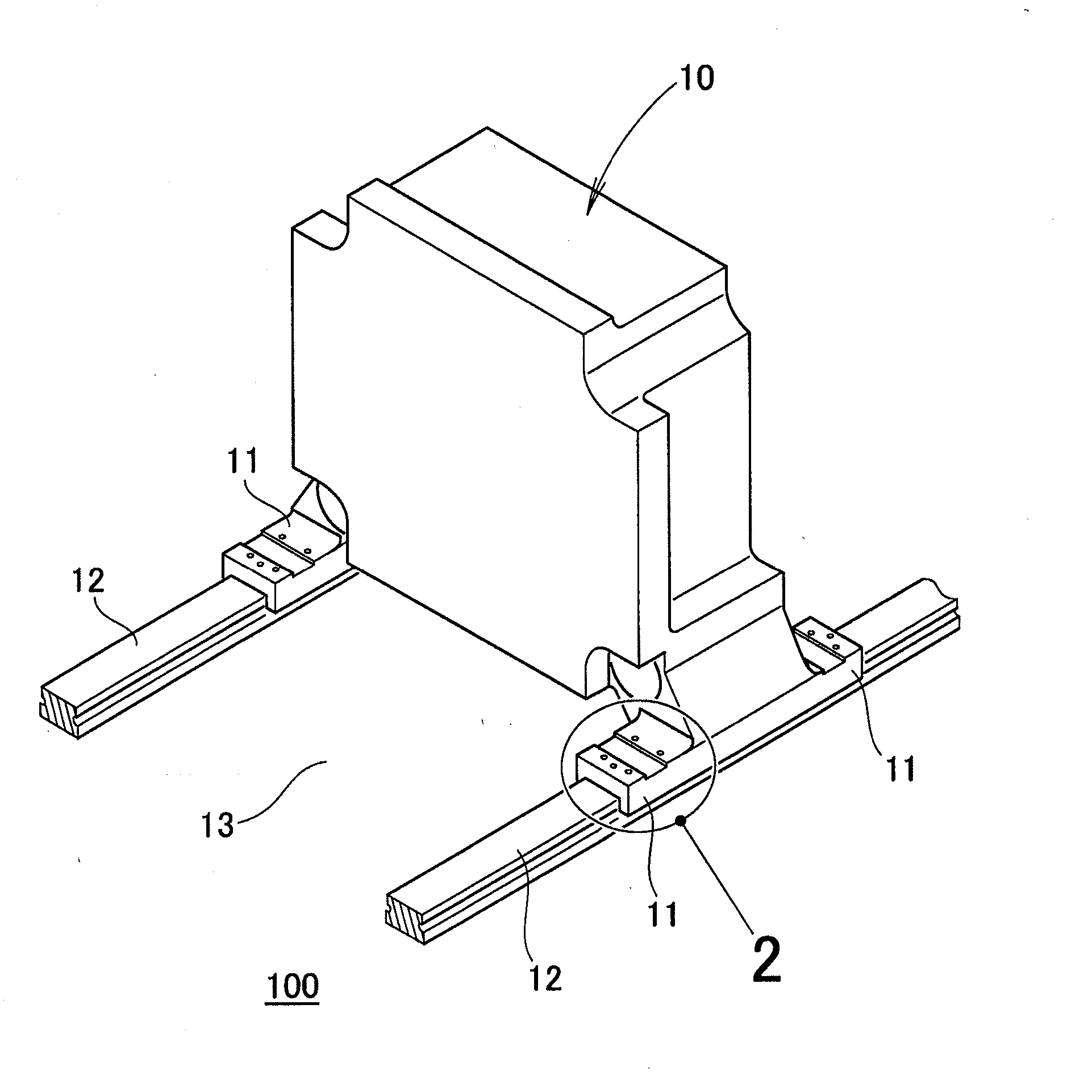
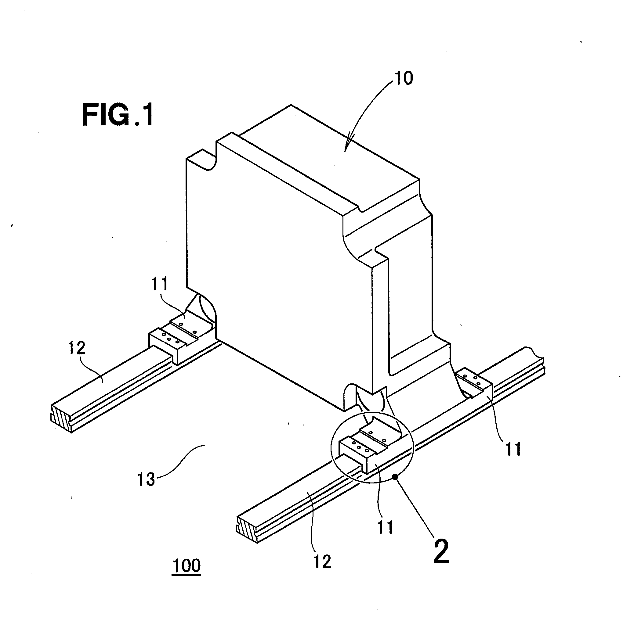
[0019]FIG. 1 is a perspective showing an embodiment of a movable platen support structure 100 of the present invention, which is provided in an injection molding apparatus for supporting a movable platen 10 of the injection molding apparatus. The movable platen 10 has a total of four leg sections 11 provided on a lower end section thereof and spaced apart from one another both in a width direction of the platen 10 and in a moving direction of the platen 10. Each of the leg sections 11 has a generally rectangular shape as viewed in top plan. Two of the leg sections 11 are placed on a left rail 12, while the other two leg sections 11 are placed on a right rail 12. The left and right rails 12 are placed on a bed 13 in parallel spaced apart relation to each other in a width direction of the bed 13.

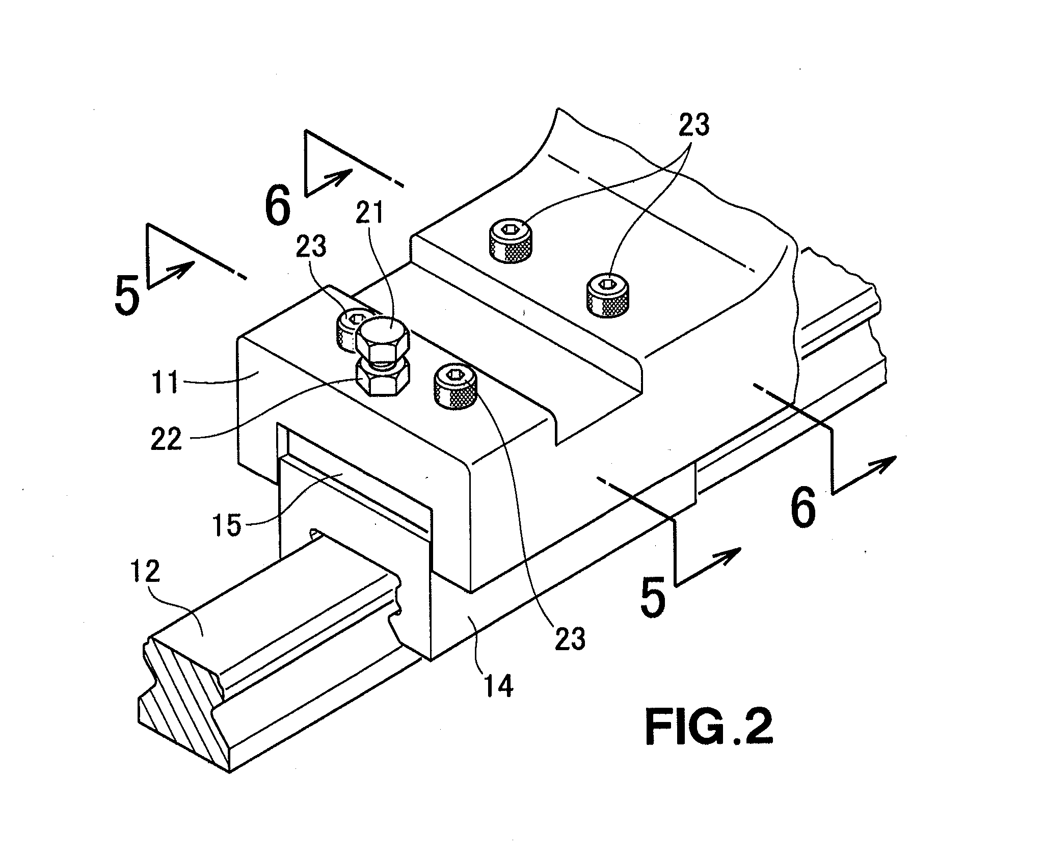
[0020]As shown in FIG. 2, for each of the leg sections 11 of the movable platen 10, the movable platen support structure 100 includes a slider 14 fitted over one of the rails 12 and a flat pla...


PUM

PropertyMeasurementUnit
widthaaaaaaaaaa
heightaaaaaaaaaa
heat conductivityaaaaaaaaaa

Abstract

A movable platen support structure includes: a linear guide mechanism via which a movable platen is provided for horizontal movement; a plurality of movable-platen height adjustment mechanisms provided in corresponding relation to leg sections of the platen, each of the height adjustment mechanisms including a flat plate placed on a corresponding slider of the guide mechanism, and an adjusting bolt screwed into the corresponding leg section of the slider and abutting at its distal end against the flat plate; and a plurality of fastening mechanisms provided in corresponding relation to the leg sections, each of the fastening mechanisms including a fastening bolt for, following the height adjustment by the adjusting bolts, fastening the corresponding leg section to the corresponding slider by being passed through the leg section and the flat plate so as to be screwed into the slider.

Description

FIELD OF THE INVENTION[0001]The present invention relates generally to an injection molding apparatus and more particularly a support structure provided in the injection molding apparatus to support a movable platen mounted on a bed for horizontal movement via a linear guide mechanism.BACKGROUND OF THE INVENTION[0002]In the conventionally-known injection molding apparatus, a mold is clamped by a fixed or stationary platen and a movable platen of a mold clamping mechanism, and a resin material is injected into the clamped mold by means of an injection machine. After the resin material hardens, the movable platen is moved away from the stationary platen to open the mold, so that a molded resin product is removed from the mold. The movable platen is reciprocally moved along a rail on the bed. In recent years, it has been getting increasingly popular to employ a linear guide mechanism called a linear guide with a view to allowing for smoother movement of the movable platen, as disclosed...

Claims


Application Information

Patent Timeline
Patent Type & Authority Applications(United States)
IPC IPC(8): B29C45/17
CPCB29C45/1744B29C45/1761B29C45/661B30B15/007
Inventor NISHIZAWA, TATSUHIKOMURATA, ATSUSHIYAMAGUCHI, ISAMUSHIOIRI, KIMIAKI
Owner NISSEI PLASTIC IND CO LTD
Why Eureka
Try Eureka